Hardware Reference
In-Depth Information
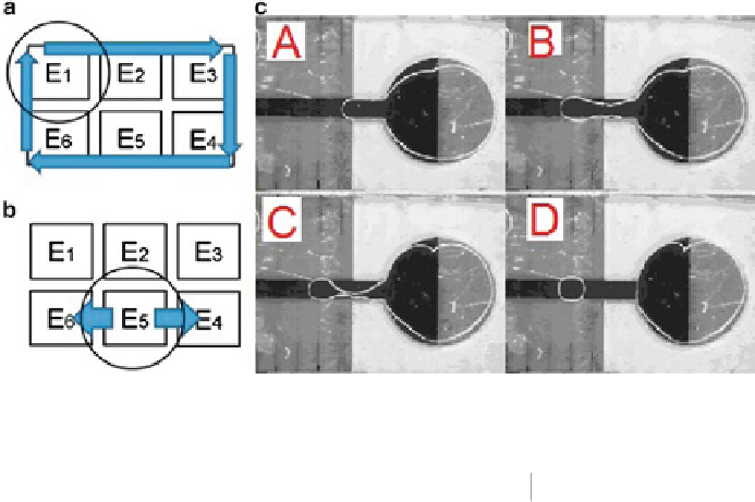
Fig. 3.3
Movement of droplets for (
a
) mixing; (
b
) splitting; (
c
) dispensing [
24
]. Steps A-D show
the procedure of pulling a droplet from the reservoir
Tabl e 3. 3
Actuation
sequences for electrodes
in the mixer
Electrodes
1
2
3
4
5
6
Actuation sequences
(ordered in time)
v
1
0
X
X
X
0
0
v
1
0
X
X
X
X
0
v
1
0
X
X
X
X
0
v
1
0
X
X
X
X
v
2
0
v
2
activation statuses are different. For example, in [
8
], the actuation voltage required
to move a droplet is 7.2 V, while the lowest voltage required to dispense a 300 pl
droplet from a reservoir is 11.4 V. Thus in the memory of the controller, these non-
zero elements of actuation matrices are recorded as the value of the corresponding
control voltages. In the following parts, we use “0” and “X” to represent deactivated
and “don't-care” status of electrodes, respectively. We also use “
v
1
”and“
v
2
”to
represent the activated status in terms of different voltages for electrodes in mixing
and splitting operations. As shown in Fig.
3.3
a, operation Mix 1 is performed on an
electrode array with two rows and three columns; at the end of mixing, the product
droplet will be split into two smaller droplets, as shown in Fig.
3.3
b. During the
mixing operation, suppose the droplet is moved counterclockwise along the loop
consisting of six electrodes. At each clock cycle, the droplet will be moved from the
current electrode to an adjacent electrode. Suppose that at time instant (clock cycle)
t
0
, the droplet rests on electrode E
1
. The actuation sequence for each electrode is
calculated and listed in Table
3.3
, and the last row in Table
3.3
corresponds to the
split operation after the completion of mixing. From Table
3.3
, we find that at each