Hardware Reference
In-Depth Information
a
b
Acrylic
ITO
Oil
SU8
gasket
Droplet
CYTOP
Dielectric layer
Electrode (L)
Silicon dioxide
Al
Interconnect
Substrate
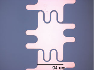
Fig. 1.4
(
a
) Electrodes of a silicon-based biochip [
25
]; (
b
) side view [
25
]
1.1.3.1
Droplet Visualization System
Cameras can be used to record the movements of multiple droplets on the biochip
simultaneously. The setup of the droplet visualization system is shown in Fig.
1.5
[
26
]. By analyzing the images captured by the cameras, droplet dispensing,
transportation, and mixing can be monitored. An example is shown in Fig.
1.6
[
26
].
One KCl droplet and one fluorescein droplet are mixed by repeating the splitting
and merging operations. The time-lapsed images obtained from the top view show
the procedure by which the fluorescein is diffused inside the droplet. Finally, the
fluorescein will be distributed homogeneously inside the merged droplet.
When the bioassay is being conducted, the control software compares the images
of the droplets in each intermediate step with the reference image of a fully-mixed
droplet. In this way, the control software can determine the extent to which the
mixing operation has approached completion [
27
]. In Sect.
2.2.1
, we will show that
the droplet visualization system can also be developed for error detection and for
automatic tracking of droplets on biochips.


