Hardware Reference
In-Depth Information
b
F
(unit:
fm
*L)
1.2
1
a
0.8
0.6
F
a
1
0.4
Contact line
0.2
0
D
Gap between electrodes
1
1.2
1.4
1.6
1.8
2
||
F
D
||
d
||
F
||
1.6
1.4
c
1.2
1
F
D
0.8
0.6
1
Contact line with
diagonal electrode
0.4
0.2
0
1.05 1.151.251.351.451.551.651.751.851.952.052.15
D
Gap between electrodes
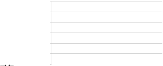
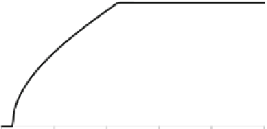
Fig. 6.12
(
a
) The force applied to the droplet when a non-diagonally adjacent electrode is
actuated; (
b
) relationship between the diameter of the droplet and the force F appliedtothe
droplet; (
c
) the force F
D
applied to the droplet when a diagonally adjacent electrode is actuated;
(
d
) relationship between the diameter of the droplet and
k
F
D
k
k
F
k
in Fig.
6.12
a. According to the principle of EWOD, the total electrowetting force F
applied to the droplet can be written as [
16
]:
F
D
f
m
L
sin
˛;
(6.6)
where L is the diameter of the droplet, and the angle ˛ is shown in Fig.
6.12
a[
16
].
The parameter f
m
is the driving force per unit length of the contact line [
16
], which
is determined by the surface characteristics of the device and the actuation voltage
applied to the electrode. For a given liquid in the droplet and a given biochip, f
m
can be considered as a constant [
16
].
For a typical EWOD device, the size of the square electrodes is 1
1 mm. As
shown in Fig.
6.12
a and c, there is a gap between the two adjacent electrodes. The
gap between two adjacent electrodes in the typical EWOD device is 20 m [
17
].