Biomedical Engineering Reference
In-Depth Information
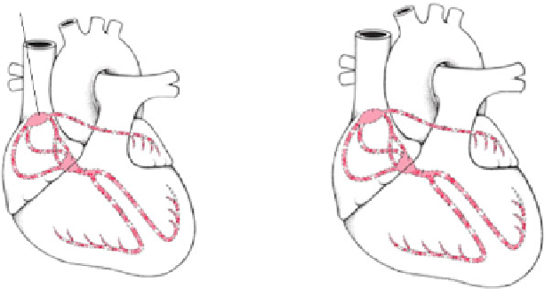
Fig. 8.4
The electrical conduction and landmarks of the heart system
and model validation using a model checker to achieve considerable advantages in
heart system modelling.
Figure
8.4
(a) shows the more significant components and the impulse conduc-
tion path in the entire heart system. The heart is a muscle with a special electrical
conduction system. The system comprises two nodes (special conduction cells) and
a series of conduction fibres or bundles (pathways). For modelling the heart sys-
tem, we have assumed eight landmark nodes (A, B, C, D, E, F, G, H) in the whole
conduction network, as shown in Fig.
8.4
(b), which control the whole heart system.
These landmarks were identified via a literature survey [
24
,
30
] and extensive dis-
cussions with a cardiologist and a physiologist. Centimetres per second (cm/sec) is
a basic unit to measure the conduction speed and milliseconds (ms) is a basic unit
to measure the conduction time.
We now introduce the necessary elements we use to define the heart system for-
mally.
Definition 1
(The heart system) Given a set of nodes
N
, a transition (conduction)
t
is a pair
(i, j )
, with
i, j
∈
N
. A transition is denoted by
i
j
. The heart system is
a tuple HSys
=
(N,T,N
0
, TW
time
, CW
speed
)
where:
•
={
}
N
is a finite set of landmark nodes in the conduction
pathways of the heart system;
A
,
B
,
C
,
D
,
E
,
F
,
G
,
H
•
T
is a set
of transitions to represent electrical impulse propagation between two landmark
nodes;
⊆
N
×
N
={
A
→
B
,
A
→
C
,
B
→
D
,
D
→
E
,
D
→
F
,
E
→
G
,
F
→
H
}
•
N
0
=
A is the initial landmark node (SA node);


Search WWH ::

Custom Search