Environmental Engineering Reference
In-Depth Information
(a)
t=10s
,
y=0
x
10
−
3
14
12
10
8
6
4
2
0.04
0.05
0.06
0.07
0.08
0.09
x
(b)
t=17
s, y=0
x 10
−3
18
(d)
1
16
12
10
8
4
2
0
0.08
0.09
0.1
0.11
0.12
0.13
0.14
x
(c)
t=20
s
, y=0
x 10
−3
18
16
14
12
10
8
6
2
0.09
0.1
0.11
0.12
0.13
0.14
0.15
x
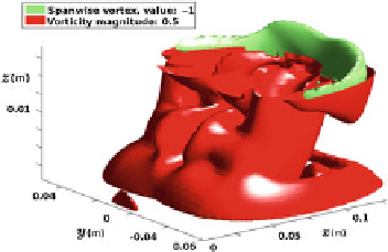
Fig. 3 a
-
c
Velocity field in the vertical symmetry plane.
d
Isovorticity surfaces of the dipole
structure. The
top
was removed to see the spanwise vortex
is away from the bottom. It is important to remark that this vortex is located in front
of the dipole (the dipole is roughly delimited by the red surface).
3.2 Periodic Forced Flow, S
=
0
.
02
The other case we studied is the flow under a periodic forcing. The values of Strouhal
and Reynolds numbers are respectively
S
=
.
=
,
000. Figure
4
shows
the isovorticity surface of the spanwise vortex for three different times (15, 20 and
40 s). The data we show correspond to times in the interval 0
0
02 and
Re
1
5
T
, that is,
over a half period. Otherwise we include only positive values of y to better visualize
the structure of the vorticity field. The spanwise vortex appears approximately at
t
<
t
<
0
.
10 s. As in the previous case, the vortex detaches from the bottom as it moves.
However it moves slowly. At
t
=
=
15 s (Fig.
4
a), the vortex is located at
x
=
4cm,
whereas at
t
8 cm. As we can see in
the figure this spanwise vortex has never a horseshoe shape as in the pulsating flow.
Finally at
t
=
20 (Fig.
4
b) the vortex has moved to
x
=
40 s (Fig.
4
a), the shape of the spanwise vortex has been completely
modified if we compare with the shape at
t
=
=
15 s and at
t
=
20 s.


Search WWH ::

Custom Search