Environmental Engineering Reference
In-Depth Information
Flow dynamics around the L-valve have been investigated and reported exten-
sively in previous studies (Chan et al.
2009
; Chovichien et al.
2013
; Knowlton
and Hirsan
1978
; Woodcock and Mason
1987
; Yazdanpanah et al.
2012
). Different
models have been proposed to describe the hydrodynamic behaviors of the valve.
Almost all models are found to be derived from L-valve operations under ambient
environment, while actual practical applications involve high temperature and/or
high pressure conditions. Furthermore, validation of these models to describe L-
valve behaviours at elevated temperature or pressure has not been tested so far. The
limitationmight be caused by the difficulties in terms of solids andmaterials handling
at high temperature or pressure.
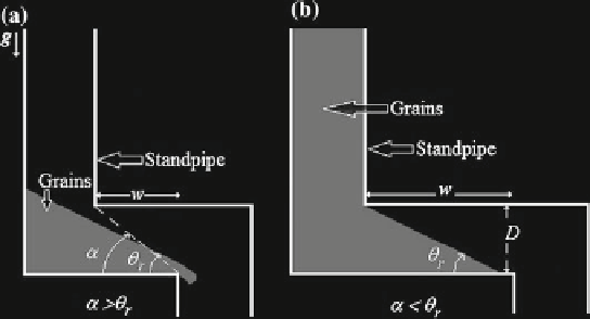
In Fig.
1
we depict an L-valve. It consists of an horizontal pipe joined to an upper
standpipe through an elbow, meanwhile the other edge of the horizontal pipe is joined
to a lower standpipe. The height of the standpipe is H whereas the height of the lower
one is not important. The slope of the dashed line defines the L-valve angle,
ʱ
. Such
slope is defined as
tan
where D s the pipe's diameter and
w
is
the distance among the adjacent, exterior face walls of pipes. Notice that if
(ʱ)
≡
tan
(
D
/
w
),
ʱ>ʸ
r
(Fig.
1
a) a gravity flow there occurs, whilst, if
ʱ
≤
ʸ
r
(Fig.
1
b) the gravity flow will
be arrested.
Currently, in many practical applications the granular column in the standpipe
will be mobilized through the application of aeration at a rate Q. Depending on
the intensity of the injected gas flow several types of solid flow can be developed
(Chan et al.
2009
; Chovichien et al.
2013
; Knowlton and Hirsan
1978
; Yazdanpanah
et al.
2012
, see Fig.
2
). Despite it, the particles flow in the dense phase mode due to
the gravity force and this phase is very important to establish the pressure drops and
the relative solid-gas velocity across the solid bed.
The aim of this work is to quantify the intensity of the gravity flow in an L-valve,
when the geometrical parameters of the valve allow it.
Fig. 1
Depicts of the transversal sections (at the
middle part
)ofanL-valve:
a
the L-valve angle,
ʱ
, overcomes the angle of repose of the granular material,
ʸ
r
and a granular gravity flow occurs.
The slope of the
dashed line
defines the L-valve angle,
ʱ
,seetext.
b
Here the angle of repose is
larger than
ʱ

Search WWH ::

Custom Search