Environmental Engineering Reference
In-Depth Information
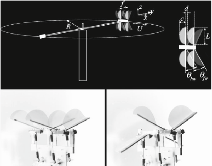
Fig. 1
To p
sketch of the experimental setup.
Bottom
photos of the flapping flyer with forewing-
hindwing phase lags 0 (
left
)and
ˀ
(
right
). Each wing has a
semi-circular
shape so that
c
=
30mm
and
L
=
60mm. The distance between the wings
d
=
1mm, so that the trailing edge of the forewing
and the leading edge of the hindwing almost touch when the wings are aligned without bending;
the stroke amplitude max
37
ⓦ
. Wings are made of 0.05mm thick Mylar
(ʸ
fw
)
=
max
(ʸ
hw
)
=
ʸ
0
=
10
−
5
Nm The leading edge is thicker (1mm) and made of
fiberglass so that it can be considered rigid and the deformation exclusively chord-wise
that gives a flexural rigidity
B
=
.
×
3
3
general be analysed simultaneously with the forewing-hindwing phase lag (Maybury
and Lehmann
2004
; Rival et al.
2011
). The motion of the wings is described using
the angles of the forewing and hindwing leading edges to the
xz
-plane,
ʸ
fw
and
ʸ
hw
,
respectively (see Fig.
1
), as
ʸ
fw
=
ʸ
0
sin
(
2
ˀ
ft
)
and
ʸ
hw
=
ʸ
0
sin
(
2
ˀ
ft
−
˕),
(1)
˕
ˀ
where
f
is the flapping frequency and the phase lag
is varied between 0 and 2
.
For 0
<˕<ˀ
the forewing is leading, whereas for
ˀ<˕<
2
ˀ
it is the hindwing
that leads. The Reynolds number Re
=
Uc
/ʽ
based on the cruising speed and the
chord length was in the range of 1,000-4,000.
The measured quantities are the cruising flight speed
U
and the consumed power
P
i
. In the study of the two winged flyer of Thiria and Godoy-Diana (
2010
) and
Ramananarivo et al. (
2011
) an additional independent setup was used to measure the
thrust force
F
by holding the flyer in a stationary position. The product of the force
Search WWH ::

Custom Search