Hardware Reference
In-Depth Information
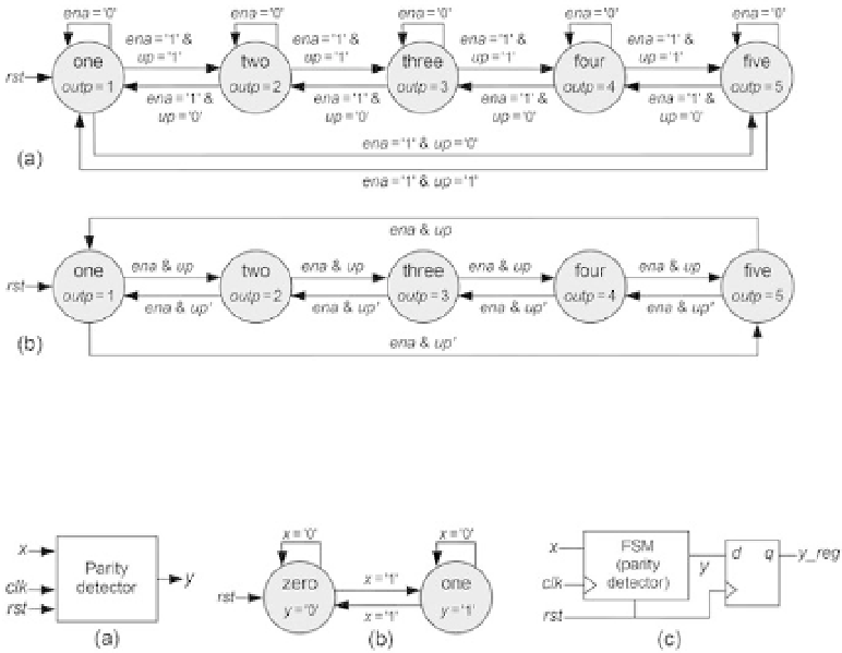
Figure 5.3
Detailed (a) and simplii ed (b) representations for a 1-to-5 counter with enable and up-down
controls.
Figure 5.4
Parity detector. (a) Circuit ports. (b) State transition diagram. (c) Hardware block diagram.
erwise, it counts from 5 down to 1, restarting then automatically from 5. Because
counters are inherently synchronous, the Moore model is the natural choice for
their implementations.
Because this machine has
M
FSM
= 5 states, and the optional output register is gener-
ally not needed in counters, the number of l ip-l ops required to implement it (see
section 5.3) is
N
FSM
= 3 if sequential, Gray, or Johnson encoding is used, or 5 for one-hot
encoding.
VHDL and SystemVerilog implementations for this counter are presented in sec-
tions 6.6 and 7.5, respectively.
5.4.2 Parity Detector
This example concerns a circuit that detects the parity of a serial data stream. As
depicted in i gure 5.4a,
x
is the serial data input, and
y
is the circuit's response. The
output must be
y
= '1' when the number of '1's in
x
is odd.
A basic solution for the case when a reset pulse is applied before every calculation
starts is presented in i gure 5.4b. In this case the parity value is the value of
y
after
the last bit has been presented to the circuit (before a new reset pulse is applied). Note