Hardware Reference
In-Depth Information
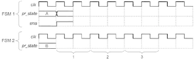
Figure 3.28
Exercise 3.15: Datapath Control
Assume that the datapath of i gure 3.22a must operate as an add-and-accumulate
circuit (ACC), accumulating in A four consecutive values of
inpB
. The data-valid pulse
(
dv
), lasting only one clock period, must again start the four-iteration procedure, after
which the resulting value must remain displayed at
ALUout
until another
dv
pulse
occurs. In summary, the operations are: 0+B
→
A, A+B
→
A, A+B
→
A, and A+B
→
A.
a) Draw an illustrative timing diagram (as in
i gure 3.22c) for an FSM that controls
this datapath.
b) Draw a corresponding state transition diagram (as in i gure 3.22d) for this machine.
After solving the problem, check section 5.4.7.