Hardware Reference
In-Depth Information
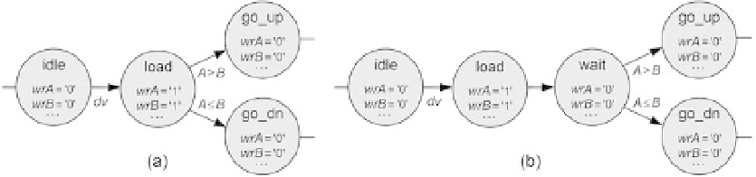
Figure 3.25
Input-data-dependent decision in a Moore-type control unit. (a) Incorrect. (b) correct.
i gure
3.25a the data-valid bit causes the machine to move from the
idle
state to the
load
state; in the latter,
wrA
=
wrB
= '1', so when the machine
leaves
that state, the proper
data will be available for comparison. Therefore, in this machine the comparison will
actually be between the data values previously stored in A and B (a mistake). This was
i xed in i gure 3.25b with the inclusion of a wait state. (Recall that in a Mealy machine
the wait state is not needed, but the Mealy approach is rarely adopted in datapath-
related applications.)
A and B and then compared to decide where the machine should go next. In
3.14 Exercises
Exercise 3.1: Moore and Mealy Circuits
a) Just by looking at the circuit of i gure 3.4e, how can you tell that it is a Moore
machine?
b) How can you tell that the circuit of i gure 3.6d is a Mealy machine?
Exercise 3.2: By-Hand Design of a Moore Machine #1
We saw in section 3.7 that the number of DFFs and the amount of combinational
logic needed to build an FSM can vary substantially with the encoding style chosen.
In the “by-hand” design of section 3.3, sequential binary encoding was employed (e.g.,
pr_state
= “00” for state
zero
, “01” for state
one
, “10” for state
two
, and “11” for state
three
).
a) Redo that design, again “by hand,” using Gray code (state
zero
→
“00”,
one
→
“01”,
“10”).
b) Redo it again, now using true one-hot code (state
zero
two
→
“11”,
three
→
→
“0001”,
one
→
“0010”,
two
“1000”).
c) Compare these three solutions (sequential, Gray, and one-hot). Which requires the
fewest DFFs? Which requires the least combinational logic? Which has the best time
predictability for the output?
→
“0100”,
three
→