Hardware Reference
In-Depth Information
Figure 3.12
Reset options (a) generated by an RC circuit, (b) generated by a specialized reset chip, and (c)
generated by another circuit possibly belonging to the same system as the FSM.
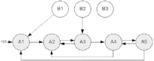
Figure 3.13
FSM with a nonconvergent external state (B3 causes deadlock).
works as a secondary machine, or a watchdog circuit). The i rst two cases are related
to the power supply, so they are power-related resets, whereas the last one can be
produced at any time.
As a i nal comment, it is important to mention that there are applications in which
reset is not necessary, either because the initial state is not important or because it is
set automatically by another signal (assuming that the machine is not subject to
deadlock). However, that is rarely the case, so the exclusion of reset should only be
done after very careful design analysis.
Additional details on FSMs' initial state and deadlock are given in the next section.
3.9 Safe State Machines
The concept of safe state machines concerns deadlock-proof implementations.
Figure 3.13 shows an FSM with i ve states (A1-A5), assumed to be encoded with
three-bit values, thus resulting in three states (B1-B3)
outside
the machine. The machine
can start from or move to an external state when no proper reset is provided (when
the DFFs' initial state is arbitrary) or because of noise during regular operation (which
might l ip one or more encoding bits). In this example the machine is able to auto-
matically recover when state B1 or B2 occurs (converging to state A1 or A3, respec-
tively), but it gets deadlocked if state B3 happens.