Hardware Reference
In-Depth Information
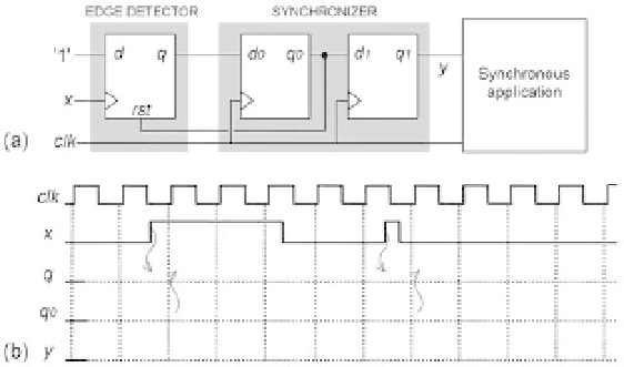
Figure 2.21
e) Note that the second pulse of
x
is shorter than one clock period and does not
coincide with any positive clock transition. Is the overall circuit able to capture this
pulse?
f) Is
y
subject to glitches? Explain.
Exercise 2.5: Fast Synchronized One-Shot Circuit #2
This exercise is an extension to the previous one. Figure 2.21a shows another synchro-
nized one-shot circuit capable of detecting short pulses at the input while still produc-
ing a one-clock-period-long pulse at the output. All involved signals are included in
i gure 2.21b, with the plots for the clock and for the input (
x
) already completed (some
helping arrows were also included in the i gure).
a) Draw the waveforms for
q
,
q
0
, and
y
. Do not forget to leave a little delay between
a signal transition and the corresponding response.
b) What are the minimum and maximum durations (in clock periods) of
q
?
c) What are the durations (in clock periods) of
q
0
and
y
?
d) At which clock edge (i rst, second, etc.) after
x
goes up does
y
go up?
e) Note that the second pulse of
x
is shorter than one clock period and does not coin-
cide with any positive clock transition. Is the overall circuit able to capture this pulse?
f) Is
y
subject to glitches? Explain.
g) Compare this circuit to that in i gure 2.20 and comment on the respective advan-
tages and disadvantages.
Exercise 2.6: Pipelined Construction
Figure 2.22 shows a complete two-stage pipeline, with L
i
and R
i
representing the logical
blocks and the registers (DFFs), respectively. The propagation delays are also included
in the i gure, with low-to-high and high-to-low delays considered to be equal.