Hardware Reference
In-Depth Information
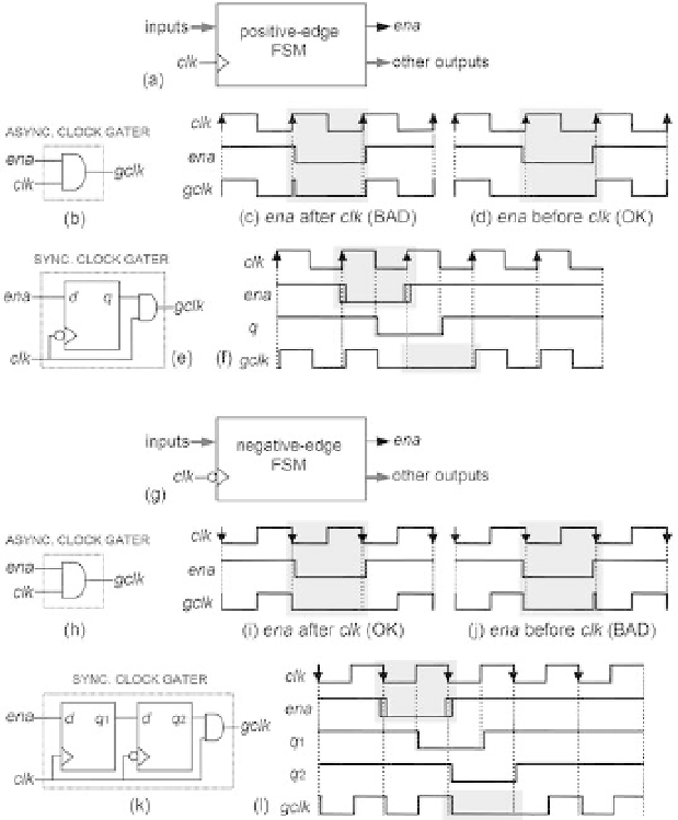
Figure 2.8
Clock gating circuits. (a-f) For positive-edge-triggered FSMs. (g-l) For negative-edge-triggered
FSMs. Asynchronous (good and bad) solutions are shown in (b) and (h), and synchronous solu-
tions (usually recommended) are presented in (e) and (k), all accompanied by illustrative timing
diagrams.