Hardware Reference
In-Depth Information
9 end entity;
10 -------------------------------------------------
11 architecture pointer_based of serial_receiver is
12 begin
13
14
process (clk, rst)
15
variable i: natural range 0 to 4;
16
begin
17
18
--Pointer (i):
19
if (rst='1') then
20
i:= 0;
21
elsif falling_edge(clk) then
22
if (i=0 and dv='0') or i=4 then
23
i:= 0;
24
else
25
i:= i + 1;
26
end if;
27
end if;
28
29
--Registered LUT (for y):
30
if rising_edge(clk) then
31
case i is
32
when 0 => y <= y;
33
when 1 to 4 => y(i-1) <= x;
34
end case;
35
end if;
36
37
end process;
38
39 end architecture;
40 -------------------------------------------------
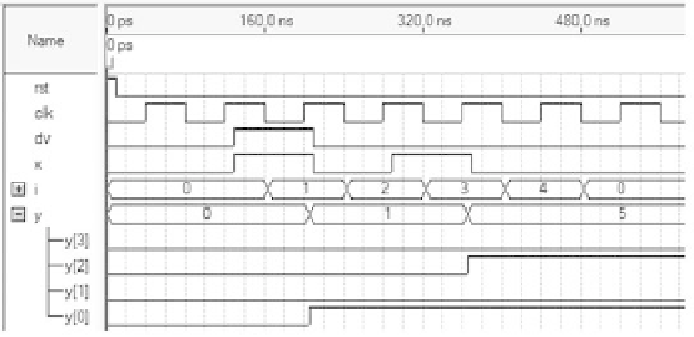
Simulation results are shown in i gure 15.5. Note that the data (
dv
and
x
) and the
register (
y
) are updated at the positive clock edges, whereas the pointer (
i
) changes at
the negative clock transitions. Note also that the sequence received in
x
is '1', '0', '1',
Figure 15.5
Simulation results from the VHDL code for the serial data receiver of i gure 15.4b.