Hardware Reference
In-Depth Information
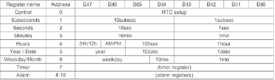
Figure 14.13
PCF8593 registers.
Data is written to registers 0 to 7, which comprise the clock and calendar; then
registers 2 to 4 are read (thus the initial address for reading is different from that for
writing), which contain clock information concerning seconds, minutes, and hours.
The following data are written (assuming that the present time and date are 1:30 pm
of Christmas day): Control = “00000000”; Subseconds = “00000000” (0.00 s); Seconds
= “00000000” (00 s); Minutes = “00110000” (30 min); Hours = “00010011” (13 h, 24-h
option selected); Date = “00100101” (date 25); Month = “00010010” (month 12).
A detailed state transition diagram for this problem is presented in i gure 14.14,
based directly on i gures 14.10 and 14.11. Either a category 2 or a category 3 machine
can be used to implement this kind of circuit; the latter option was chosen here,
whereas the former option will be employed in the next section, which deals with the
SPI interface. This FSM is simple enough to also be implemented using the pointer-
based technique described in chapter 15.
Figure 14.14 was divided into three parts. The overall FSM is presented in i gure
14.14a, where six common states plus write and read blocks are shown. Because the
wr
and
rd
commands are produced by two switches (long signals) in the experiments,
the state called
hold
was included after
stop
to force the machine to wait until
wr
= '0'
occurs before returning to
idle
(long
rd
= '1' is accepted because continuous reading is
wanted here, although this could also be done by repeating only the data-reading
states). It was chosen not to have
hold
wait for
t
BUF
because another immediate write
sequence is very unlikely to be needed in this kind of application. The write sequence
is shown in i gure 14.14b; seven bytes of data (listed under the dashed rectangle) must
be transmitted, so the pair of states inside the dashed rectangle must be repeated seven
times. Finally, the read sequence is presented in i gure 14.14c; three bytes of data (listed
under the dashed rectangle) must be received (and stored), so the pair of states inside
the dashed rectangle must be repeated three times. We have elected to use a pointer
(
j
) to repeat the
wr_data-ack3
pair in the transmitter and to use three separate pairs to
repeat the
rd_data-ack
(or
noack
) pair in the receiver.