Hardware Reference
In-Depth Information
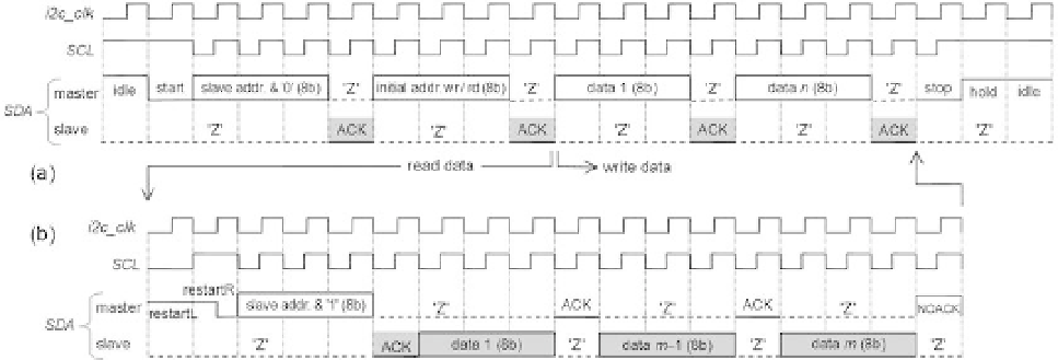
The write procedure (i gure 14.9a) begins with a start pulse, followed by the i rst
byte, which contains the slave's seven-bit address plus a '0' appended to its right-end
(this '0' informs the slave that a write procedure will occur). The corresponding slave
responds with an acknowledgment bit (= '0'). The second byte is then issued by the
master, containing the initial memory address where the writing must occur, to which
the slave responds with another ack bit. After this, data writing begins, which can
consist of any number of bytes, until the master ends the operation with a stop pulse.
The read procedure (i gure 14.9b) is exactly the same as the write procedure
up to line 1, or up to line 2 if the same initial address is used for writing and for
reading. After line 2 another start pulse is issued by the master, followed by the seven-
bit slave's address, this time with a '1' appended to its right-end (informing that a
read operation will occur), to which the slave responds with a i nal ack bit. After this
point the slave issues the data and the master issues the ack bit. Again, any number
of bytes can be transferred, until a no-ack (= '1') bit is issued by the master, followed
by a stop pulse.
The repetition seen in i gure 14.9b (before line 2) is sometimes referred to as
dummy
write
. It is necessary because I
2
C also permits reading from wherever the address
pointer sits, in which case the entire portion before line 2 is omitted. In other words,
the dummy write resets the address pointer to a specii c position.
The diagram of i gure 14.9 is shown in a temporal fashion in i gure 14.10, now
with all waveforms to be used in the experiments explicitly shown. This diagram is
based directly on i gure 14.8c. Because
t
HD_DAT
= 0 (i gure 14.8b), only a single clock is
actually needed. Observe the safe construction of the restart sequence, needed for
reading, which takes two clock cycles (left and right portions). Note also the inclusion
of a hold state at the end, which waits for
wr
= '0' (and also
rd
= '0' if sequential
Figure 14.10
Detailed I
2
C signals for (a) writing and (b) reading (compare to the sequences in i gure 14.9).