Hardware Reference
In-Depth Information
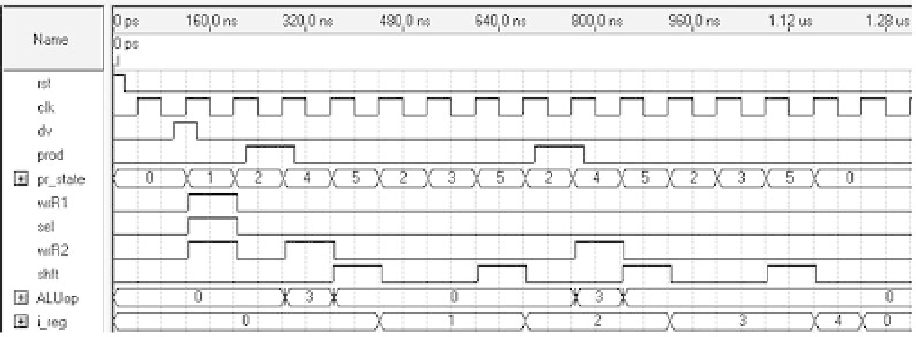
Figure 12.1
Simulation results from the VHDL code for the control unit of i gure 11.12b, for
N
= 4, which
controls a multiplying datapath.
std_logic_vector
(industry standard). Note that mode
buffer
is used this time for
y
, so
y
can be associated directly with
y_reg
.
The architecture, called
moore_fsm
, is in lines 13-89. As usual, it contains a declara-
tive part and a statements part, with three processes in the latter.
The declarative part of the architecture (lines 15-21) contains FSM- and auxiliary-
register-related declarations. In the former the enumerated type
state
is created to
represent the machine's present and next states. In the latter the signals
y_reg
,
i
, and
i_reg
are created to deal with the auxiliary registers. Note that two auxiliary registers
are needed in this example: for the main (actual) output (
y
) and for the output that
operates as an auxiliary pointer (
i
) to the FSM.
The i rst process (lines 26-35) implements the auxiliary register, similarly to the
template, except for the fact that there are now two auxiliary registers.
The second process (lines 38-45) implements the FSM's state register, exactly as in
the template.
The third and i nal process (lines 48-87) implements the entire combinational logic
section. It is just a list of all states, each containing the output values and the next
state. Observe that in the (originally) recursive equations (lines 53, 63-64, and 75-76),
i_reg
and and
y_reg
appear on the right-hand side instead of
i
and
y
themselves (as
proposed in the template). As usual, note that in each state the output values are
unique because in a Moore machine the outputs depend only on the state in which
the machine is. Another important aspect can be observed in lines 64-65 and 76-77;
note that i rst a value is assigned to the entire vector
y
(lines 64 and 76), then one of
its bits,
y
(
i
−
1), is overwritten (lines 65 and 77).