Hardware Reference
In-Depth Information
b) Compare the results above. Was the difference between the two strategies more
relevant for sequential or one-hot encoding? Explain.
Exercise 9.2: Blinking Light
This exercise concerns the blinking light FSM of i gure 8.12c.
a) Which of the two timer control strategies (#1, section 8.5.2, or #2, section 8.5.3),
if any, can be adopted in the implementation of this FSM?
b) Implement it using VHDL. Check whether the number of DFFs inferred by the
compiler matches the prediction made in section 8.11.1 for each encoding option
(sequential, Gray, Johnson, and one-hot). Recall that the predictions must be adjusted
in case the clock frequency is different from 50 MHz.
c) Physically test your design in the FPGA development board. Use two switches to
produce
rst
and
ena
and use an LED to display the output.
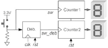
Exercise 9.3: Switch Debouncer
This exercise concerns the switch debouncer of i gure 8.16c, which was inserted into
the circuit of i gure 9.3. The i gure also shows two counters; the signal produced
by the switch (
sw
) acts as clock to counter1, and its debounced version (
sw_deb
) acts
as clock to counter2. Every time the pushbutton is pressed (or a toggle switch is
l ipped), both counters will be incremented, but counter1 might occasionally be
incremented by more than one unit (the more the switch bounces, the bigger the
difference between the values on the displays). Assume a 2-ms debouncing interval
(check the clock frequency in your development board) and sequential encoding for
the FSM, with the counters able to count from 0h to Fh.
a) Which of the two timer control strategies (#1, section 8.5.2, or #2, section 8.5.3),
if any, can be adopted in the implementation of this FSM?
b) Estimate the number of DFFs needed to build the complete circuit. Does this
number depend on the answer to part a above?
c) Design the circuit using VHDL. Check whether the number of DFFs inferred by the
compiler matches your prediction.
Figure 9.3