Hardware Reference
In-Depth Information
Figure 8.34
a) Draw a l owchart for the combined solution of i gure 8.33b (debouncer plus memory
in one FSM).
b) Draw a Moore-type state diagram corresponding to the l owchart presented above.
c) Assuming that sequential encoding is used and that the debouncing time interval
is 1 ms, with
f
clk
= 50 MHz, calculate the number of l ip-l ops needed to build this
machine.
d) If the solution of i gure 8.33a were employed, with the debouncer included, how
many l ip-l ops would be required?
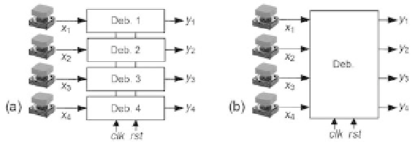
Exercise 8.8: Independent Multisignal Debouncer
Figure 8.34 shows four mechanical switches for which debouncers are needed. In i gure
8.34a a complete debouncer for each signal is considered, whereas i gure 8.34b consid-
ers a “combined” approach. Because the timer is the most expensive part, if a single
timer could be used in the latter it would already represent a major gain. In this exer-
cise the switches are independent of each other, so they might be activated simultane-
ously. Assume a 1-ms
minimum
debouncing interval, a 50-MHz clock, and sequential
encoding for the FSMs.
a) How many l ip-l ops are needed to implement the option in i gure 8.34a, employing
the debouncer of i gure 8.16c?
b) Draw a state transition diagram for an FSM capable of implementing the combined
debouncer of i gure 8.34b.
c) How many l ip-l ops are needed to implement your combined circuit?
Exercise 8.9: Dependent Multisignal Debouncer
Figure 8.35 shows a keypad (see details in exercise 5.14) for which debouncers are
needed. Note that this exercise is an extension to that above, with the difference that
now the signals are no longer independent of each other. Because only one key is
supposed to be pressed at a time, the only valid codewords are “1111” (no key pressed),
“0111” (key in row 1 pressed), “1011” (key in row 2 pressed), “1101” (key in row 3