Hardware Reference
In-Depth Information
are 1, 2, 4, and 8 Hz. The next speed must be selected every time the pushbutton is
pressed, returning to 1 Hz after passing 8 Hz. One alternative (among others) is pre-
sented in i gure 8.32, which consists of a cascade of FSMs. The i rst can be a debouncer
+ one-shot converter (similar to i gure 8.18b), the second can be a reference-value
dei ner (similar to i gure 8.18c), and the third the light blinker proper (i gure 8.12c).
The purpose of the i rst pair of FSMs is to produce
T
ref
, which is then used as time
parameter for the blinker. Assume a 1-ms debouncing interval, a 50-MHz clock, and
sequential encoding for the FSMs.
a) Calculate the four values of
T
ref
(one for each speed); for example, for 1 Hz,
t
ref
= 0.5
s, so
T
ref
= 25
10
6
clock cycles.
b) Draw a block diagram for your solution, splitting the big block of i gure 8.32 into
two blocks.
c) Show the state transition diagram for each FSM used in this circuit.
d) How many DFFs are needed to build the entire circuit?
⋅
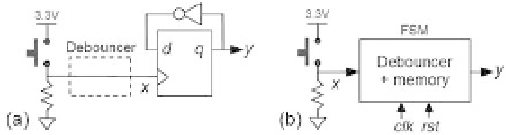
Exercise 8.7: Pushbutton Debouncer plus Memory
Figure 8.33 shows a pushbutton that must be debounced and also “memorized,”
such that the stored value gets inverted every time the pushbutton is pressed (as in
the stopwatch used by football referees, which alternately runs and stops every time
the pushbutton is pressed). If a debouncer were not needed, the trivial solution of
i gure 8.33a could be used, in which
x
is connected directly to the clock input of a
DFF (due to the inverted version of
q
connected back to
d
, it resembles a toggle-type
l ip-l op, so every time a positive clock edge occurs, the value of
y
gets inverted).
Let us assume, however, the usual situation, in which the pushbutton must be
debounced.
Figure 8.32
Figure 8.33