Hardware Reference
In-Depth Information
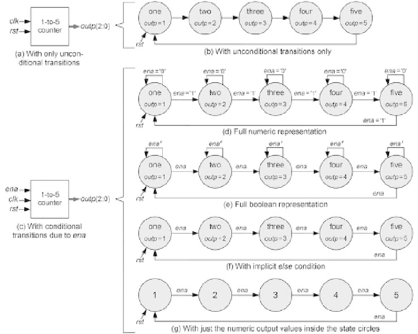
Figure 1.4
(a, b) A 1-to-5 counter with only clock and reset as inputs (the transitions are unconditional).
(c-g) The counter has an additional input (
ena
), which either enables the counter or causes it to
stop. The representations in d-g are equivalent.
input, called
ena
, which enables the counter when asserted (
ena
= '1') or causes it to
stop otherwise.
Figure 1.4b shows the FSM corresponding to the counter in i gure 1.4a. Because
there are no inputs in this circuit (except for the operational inputs, clock and reset),
it can only be a Moore machine. Note that all possible states are included and that
the value that must be produced at the output in each state is specii ed. However,
there are no specii cations for the transition conditions, which means that the transi-
tions are
unconditional
, that is, they must occur at every (positive) clock edge.
Observe that a special (simplii ed) representation is reserved for the reset signal (not
only in this example, but in all state transition diagrams). The reset signal is repre-
sented by a single arrow pointing to the state to which the machine is forced when
rst
= '1' occurs.