Hardware Reference
In-Depth Information
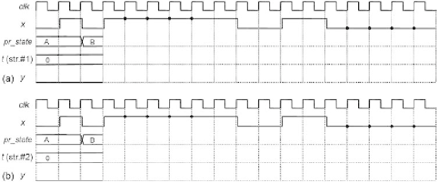
Figure 8.31
situation. Assume that strategy #1 (section 8.5.2) was adopted for the timer. (Regarding
strategy #2, see the previous exercise.)
Exercise 8.4: Analysis of Timer Control Strategies #1 and #2
Assume that the switch debouncer of i gure 8.16c was designed to operate with
T
= 4
clock cycles (more precisely, with 4 clock edges, because
x
is asynchronous).
a) Say that strategy #1 (section 8.5.2) was employed to design the timer. Complete the
timing diagram of i gure 8.31a for the given input
x
. As usual, a small propagation
delay was included between clock transitions and corresponding responses to portray
a more realistic situation. Call the states A, B, C, and D to simplify the notation.
b) Do the same for the timing diagram of i gure 8.31b, assuming now that strategy #2
was used for the timer. Is the result (
y
) the same as for strategy #1?
Exercise 8.5: Blinking Light without Reset
It was said in section 8.11.1 that the light blinker of i gure 8.12c might not require a
reset signal, even if l ip-l ops with arbitrary initial states are used to implement it.
a) Prove that if sequential encoding is used and optimal (minimal) expressions are
adopted for
nx_state
(i.e.,
d
1
and
d
0
), then this FSM can indeed operate without reset.
(Suggestion: Review sections 3.8 and 3.9 and see exercise 3.11.)
b) Show that, on the other hand, if sequential encoding is used but all “don't care”
bits are i lled with '1's, then the machine is subject to deadlock, so a reset signal is
needed.
Exercise 8.6: Blinking Light with Several Speeds
This exercise is an extension to the light blinker of i gure 8.12c, which must now
operate with a
programmable
speed, set by a pushbutton (called
spd
). The desired speeds