Hardware Reference
In-Depth Information
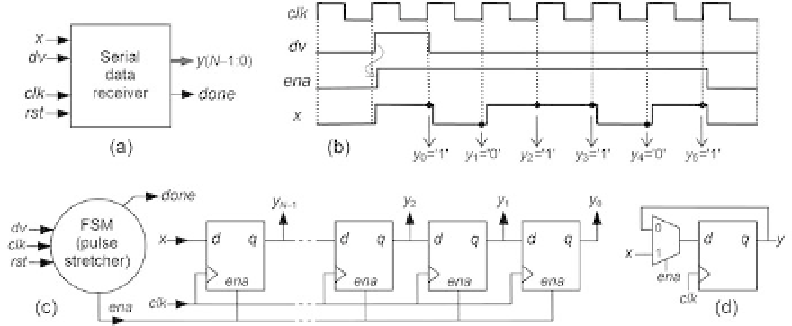
Figure 8.29
Serial data receiver. (a) Circuit ports. (b) Desired behavior (
dv
is stretched to produce
ena
). (c)
Solution with a shift register controlled by the pulse stretcher.
8.28a). The second solution is for the asynchronous case of i gure 8.27c, valid for
inputs 4 and 5; because this circuit is asynchronous, it was implemented with a Mealy
machine (i gure 8.28c). Solutions for other cases are treated in exercises 8.20 to 8.23.
Figures 8.28b and 8.28d present illustrative timing diagrams for the FSMs of
i gures
8.28a and 8.28c, respectively, for
T
= 5. It is very important that the reader examine
these diagrams carefully and check the correctness of the circuit operation.
An application for a pulse stretcher is depicted in i gure 8.29, which consists of a
serial data receiver (a deserializer). The circuit ports are shown in
i gure 8.29a. The
inputs are
x
(serial bit stream),
dv
(data valid bit, high during only one clock cycle,
informing that data storage should start), plus the conventional clock and reset. The
outputs are
y
(
N
1:0) (multibit one-dimensional register in which the received data
must be stored) and
done
(high while the machine is idle). Some of these signals are
shown in i gure 8.29b, which also highlights the fact that the i rst bit of
x
is made
available at the same time that
dv
is asserted, so data storage must start immediately.
A possible solution is presented in
−
i gure 8.29c. It consists of a shift register whose
enable input is produced by an FSM (this is a simplii ed view; the enable port of a
DFF, if not built-in, can be constructed using a multiplexer, as shown in i gure 8.29d).
When a
dv
= '1' pulse occurs, the FSM produces
ena
= '1' during
N
consecutive clock
cycles, causing
N
bits of
x
to be shifted in, thus getting stored in the
N
l ip-l ops that
comprise the shift register, producing
y
(
N
1:0).
Note that in this case the FSM is simply a pulse stretcher. Because the i rst bit of
x
is made available at the same time that
dv
is asserted, one must be careful not to
skip that bit (see section 3.10). Consequently, we can employ either an asynchro-
nous (Mealy) FSM, which would then produce the signal shown in the i gure, or a
−