Hardware Reference
In-Depth Information
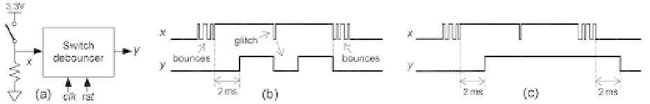
Figure 8.15
(a) Mechanical switch and debouncer ports. (b) Bounces processed by a one-sided (low-to-high)
debouncer. (c) With a two-sided debouncer.
i nally settling in the proper position, as illustrated in i gures 8.15b,c. Depending on
the switch characteristics, such bounces can last from a fraction of a millisecond up
to several milliseconds.
Switch bounces are not acceptable in several applications. A disastrous example is
when the signal produced by the switch must act as a clock to some process because
the corresponding l ip-l ops will understand the bounces as several clock pulses.
Two debouncing approaches are depicted in i gures 8.15b,c. The i rst is one-sided
(only the low-to-high transition is debounced), whereas the second is two-sided (both
transitions are debounced). The debouncing strategy here consists of checking the
input permanently (at every clock cycle) and accepting a new value only after it has
remained i xed for a certain amount of time. For example, if the debouncing time is
2 ms and the clock frequency is 50 MHz, the same result must occur 2·10
-3
×
50·10
6
= 100,000 consecutive times to be considered valid.
Note that in i gure 8.15b the one-sided debouncer automatically i lters the other
transition, but it does not protect the circuit against unexpected input transients/
glitches (caused, for example, by the switching of large current loads onto the same
power supply or by lightning).
In debouncers, glitches at the output are generally undesired because providing a
safe, clean signal is precisely the purpose of this circuit, so the optional output register
of i gure 8.2b should be employed unless
y
comes directly from a DFF (this depends
on the encoding scheme and can be checked in the compilation report equations).
A l owchart for the two-sided debouncer of
i gure 8.16a.
An initial (bad) solution is presented in i gure 8.16b. The problem here is that it
only checks the condition
x
= '1' (or '0')
at the end
of
T
clock cycles. Consequently, to
obtain a full debouncer, each transition of i gure 8.16b must be replaced with three
pure transitions, resulting in the FSM of i gure 8.16c. Although the “
i gure 8.15c is presented in
−
2” factor in the
timed
t
=
T
2 condition does not matter in this application, it was kept as a reminder
of the precise value.
Even though the input (
x
) is asynchronous, a synchronizer (section 2.3) is not
needed because
y
can change its value only after a time
T
, which is a synchronous
condition (the timer operates with the same clock as the FSM).
−