Hardware Reference
In-Depth Information
To employ the FSM approach to design a sequential digital circuit, all three requisites
listed above must be fuli lled, and also the list of states must not be too long. All sorts
of controllers (including control units for datapath-based designs) are typical examples
of circuits well suited for this design technique, as will become clear through the many
examples presented in the topic.
State machines can be of Moore or Mealy type. Both are described below.
Moore-Type State Machines
An FSM is said to be of Moore type when its output depends solely on the machine's
present state. In other words, the output is not affected directly by the input (the input
can only affect the machine's next state). The result is a fully synchronous circuit
because the output can only change when the clock ticks.
An example of Moore FSM is presented in i gure 1.3b. The circuit ports are shown in
i gure 1.3a, consisting of a data input,
x
(8-bit extended ASCII character), a data output,
y
(single bit), plus the conventional operational inputs of clock and reset. The circuit must
produce
y
= '1' when the sequence “
abc
” occurs in
x
, that is, when
x
= “01100001” (ASCII
code for
a
), followed by
x
= “01100010” (=
b
), then
x
= “01100011” (=
c
) occur.
The Moore-type state transition diagram of i gure 1.3b contains four states, called
idle
,
char1
,
char2
, and
char3
. Each state tells the value that must be produced at the
output (
y
) while the machine is in that state; note that only
char3
produces
y
= '1'
because the machine only reaches that state if the correct sequence (
abc
) is detected.
Finally, the transition conditions (on
x
, the input) are shown along the arrows.
The meaning of the state diagram of i gure 1.3b is as follows. Say that the circuit is in
the
idle
state; if
x
=
a
is received, it moves from
idle
to
char1
, otherwise it remains in
idle
;
if it is in
char1
and
b
is received, it moves to state
char2
, otherwise it remains in
char1
if
a
was received or returns to
idle
if neither
a
nor
b
was received; and so on. Note in i gure
1.3b that, because this is a Moore machine, the output depends only on the state in
which the machine is, so the output values can be written inside the state circles.
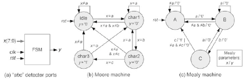
Figure 1.3
A i nite state machine that detects the ASCII sequence “
abc
”. (a) Circuit ports. Corresponding (b)
Moore and (c) Mealy state transition diagrams.