Hardware Reference
In-Depth Information
Strategy #2 is a little more difi cult to examine. This is due to the CB transition,
which can only happen with
t
t
max
, causing the FSM to enter state B without any
command to zero the timer at the next clock edge. Observe in the B-to-C transition
in the timing diagram of i gure 8.5d that
t
is still incremented when the FSM enters
state B, being only zeroed at the next clock pulse. However, in spite of this detail, the
machine operates adequately, as can be seen in the plot for
y
, which is exactly the
same as that in i gure 8.5c.
The reader is invited to examine these two timing diagrams carefully to fully under-
stand and appreciate the differences between these two timer control strategies.
<
8.6 Truly Complementary Time-Based Transition Conditions
As discussed in Section 3.8, when a circuit does not have any sort of reset mechanism,
the initial state (either '0' or '1') of its l ip-l ops upon power-up might be undeter-
mined. Say that that is the case and that our machine has a timed transition that must
span 10 clock periods, thus requiring a 4-bit counter, where 0-to-9 is the range of
interest. Since a 4-bit counter is capable of counting from 0 to 15, the initial (random)
state might fall in the 10-to-15 range. Recall from section 1.5 that the outward transi-
tion conditions in any state must be
truly complementary
(i.e., they must include all
possible combinations of the transition control signals, and obviously all just once),
so the 10-to-15 range must also be considered.
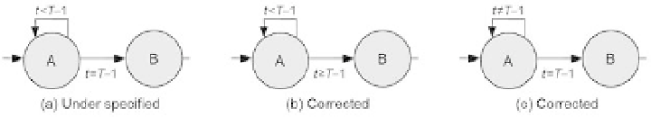
Figure 8.6a shows an example of timed machine with under-specii ed transition
conditions, which falls in the situation described above because the
t
1 range is
not covered. The problem in i xed in i gure 8.6b by assigning that range to the AB
transition. Another alternative is presented in i gure 8.6c, with the missing range
assigned to the AA transition. Either one of the last two options should be used. The
decision between one or the other depends on the application; more specii cally, it
depends on where we want the machine to be in case
t
>
T
−
>
T
−
1 happens (at power-up,
for example).
Figure 8.6
(a) Under-specii ed transition conditions (
t
>
T
−
1 range not covered). (b)
t
>
T
−
1 range assigned
to the AB transition. (c)
t
>
T
−
1 range assigned to the AA transition.