Hardware Reference
In-Depth Information
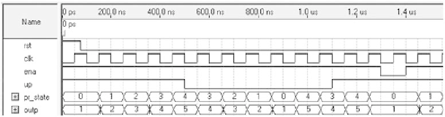
Figure 7.3
Simulation results from the SystemVerilog code for the 1-to-5 counter with enable and up-down
controls of i gure 5.3.
Simulation results from the code above are exhibited in i gure 7.3. Note that the
output changes only at positive clock transitions, counting up when
up
='1', down
when
up
='0', and stopping if
ena
='0'.
The number of l ip-l ops inferred by the compiler was three for sequential, Gray,
or Johnson encoding and i ve for one-hot, matching the predictions made in section
5.4.1.
7.6 Design of a Garage Door Controller
This section presents a SystemVerilog-based design for the garage door controller
introduced in section 5.4.5. The Moore template of section 7.3 is employed to imple-
ment the FSM of i gure 5.9c.
The i rst part of the code (
module header
) is in lines 1-4. The module's name is
garage_door_controller
. Note that all ports are of type
logic
.
The second part of the code (
declarations
) is in lines 6-10. The enumerated type
state
is created in it to represent the machine's present and next states.
The third and i nal part of the code (
statements
) is in lines 12-65. It contains two
always
blocks, described next.
The i rst
always
block (lines 14-16) is an
always_ff
, which implements the
machine's state register. This is a standard code, similar to the template.
The second
always
block (lines 19-63) is an
always_comb
, which implements the
entire combinational logic section. It is just a list of all states, each containing the
output value and the next state. Note that in each state the output value is unique
because in a Moore machine the output depends only on the state in which the
machine is.
Finally, and very importantly, observe the correct use of registers and the complete-
ness of the code, as described in comment 8 of section 7.3. Observe in particular the