Hardware Reference
In-Depth Information
to midcomplexity combinational circuits; sequential code using
process
, which is
constructed using sequential statements (
if
,
case
,
loop
,
wait
), for sequential as well
as (complex) combinational circuits;
function
/
procedure
calls; and, i nally,
compo-
nent
(that is, other design) instantiations, resulting in structural designs.
6.3 VHDL Template for Regular (Category 1) Moore Machines
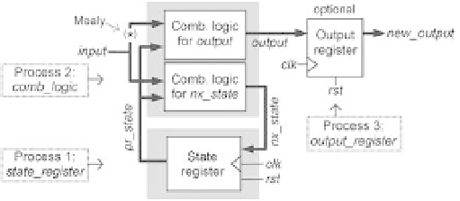
The template is based on i gure 6.2 (derived from i gure 5.2), which shows three pro-
cesses: 1) for the FSM state register; 2) for the FSM combinational logic; and 3) for the
optional output register. Note the asterisk on one of the input connections; as we
know, if that connection exists it is a Mealy machine, else it is a Moore machine.
There obviously are other ways of breaking the code instead of using the three
processes indicated in i gure 6.2. For example, the combinational logic section, being
not sequential, could be implemented without a process (using purely concurrent
code). At the other extreme the combinational logic section could be implemented
with two processes, one with the logic for
output
, the other with the logic for
nx_
state
.
The VHDL template for the design of category 1 Moore machines, based on i gures
6.1 and 6.2, is presented below. Observe the following:
1) To improve readability, the three fundamental code sections (library/package dec-
larations, entity, and architecture) are separated by dashed lines (lines 1, 4, 14, 76).
2) The library/package declarations (lines 2-3) show the package
std_logic_1164
,
needed because the types used in the ports of all designs will be
std_logic
and/or
std_
logic_vector
(industry standard).
3) The entity, called
circuit
, is in lines 5-13. As seen in i gure 6.1, it usually contains
two parts:
generic
(optional) and
port
(mandatory for synthesis). The former is
employed for the declaration of generic parameters (if they exist), as illustrated in lines
6-8. The latter is a list of all circuit ports, with respective specii cations, as illustrated
Figure 6.2
State machine architecture depicting how the VHDL code was broken (three processes).