Geoscience Reference
In-Depth Information
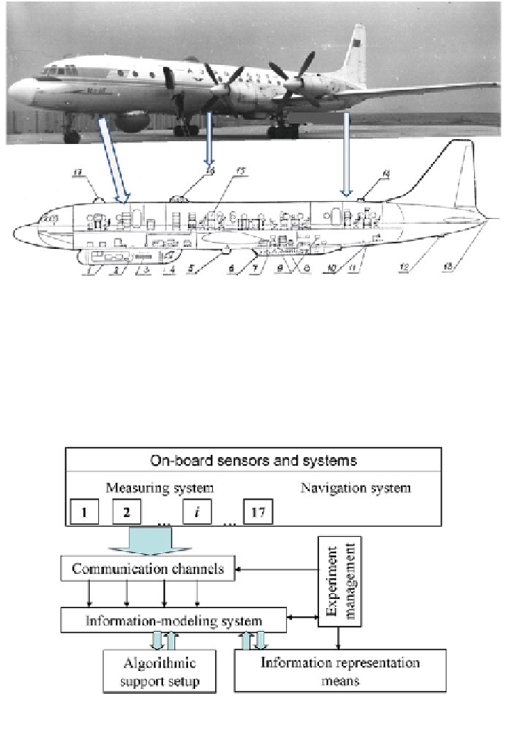
Fig. 2.4 Scheme of positioning the antenna systems and photo-hatches on-board of flying
laboratory IL-18. Notation: Antennas: 1, 3
—
radio locators with synthetic aperture, wavelengths
—
2.0 and 10.0 cm; 2, 6
—
trace polarimeters, wavelength
—
0.8 and 2.25 cm; 4
—
six-channel scanning
polarimeter, wavelength
—
0.8, 1.35, 2.25, 10, 20 and 27 cm; 7, 9
—
precision altimeter and
interferometer of side looking, wavelength
—
2.2 cm; 13
—
sub-surface sounding station of
decimetric range; Photo-hatches: 5, 10, 12
—
large-format and frame TV, aerocamera; 11, 14
—
radiometers of mm range; 16
—
trace radiometers, wavelength
—
0.8, 1.35, and 2.25 cm; 15
—
gravimetric and inertial devices; 17
—
astro-hatch
Fig. 2.5 Typical structure of on-board information-modeling system realized in flying laboratory
IL-18
flying laboratory IL-18 in Former USSR has showed
the availability of using the multi-purpose remote sensing systems under solution of
environmental problems on large territories. Unfortunately, this laboratory was
Long-term exploitation of
fl
Search WWH ::

Custom Search