Hardware Reference
In-Depth Information
a
b
0
I
1
I
2
R
1
I
out
y
z
CCII+
x
C
2
R
2
−20
C
1
R
L
I
3
−40
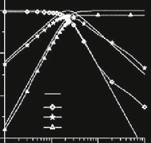
LP, BP, HP ideal
LP experiment
BP experiment
HP experiment
−60
1E+4
1E+5
Frequency (Hz)
1E+6
1E+7
c
Fig. 6.35 Filter configuration proposed by Ozcan et al. (Adapted from [
30
]
©
2003 Elsevier) (a)
The circuit configuration (b) The theoretical and measured LP, BP and HP responses (c) A typical
output waveform of the filter (input current 1 mA, 205 kHz; load resistance 10 k
ʩ
: vertical axis-
5 V/div., horizontal axis- 1
ʼ
s/div)
Abuelma
'
atti and Tasadduq Biquad Figure
6.36
shows a three input and single
output universal CM biquad proposed by Abuelma
atti and Tasadduq [
31
]. The
presented filter configuration employs six CCIIs+, two grounded capacitors and six
grounded resistors. The filter configuration enjoys independent control of
'
ω
0
and
ω
0
/Q
0
through separate grounded resistance and independent gain control through
separate grounded resistor of all the filter responses.
The various CM transfer functions for this circuit can be deduced from the
following input output equation:
C
3
R
4
I
2
þ
I
1
s
2
I
3
s
1
1
C
1
C
3
R
2
R
4
1
R
8
R
5
C
3
R
4
R
7
I
0
¼
ð
6
:
56
Þ
1
1
1
C
1
C
3
R
2
R
4
R
6
s
2
þ
s
þ
From Eq. (
6.56
), the following five generic filter responses can be obtained: LPF:


Search WWH ::

Custom Search