Geology Reference
In-Depth Information
the grain where the
c
‐axis is not matched exactly with
respect to its general direction within the grain. This mis-
match develops when the dendrites in the skeletal layer
protruded in the liquid and are subjected to local distur-
bances. Therefore, they grow at slightly different orienta-
tions, forming subgrains, and eventually merge to form a
“family” of closely oriented crystalline entity known as
grain. Actually, the conventional thin sectioning technique
using warm plates inadvertently show the cellular struc-
tures of sea ice grains because of the impregnation of brine
along the boundaries due to melting. This together with
smearing of brine on both the surfaces of thin sections
does not assist in the clarifications of the role of individ-
ual brine pockets and the subgrain boundaries.
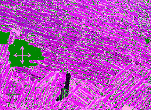
Figure 2.35 is a photograph of a horizontal thin section
of columnar grained, first‐year ice at a depth of 2.05 m,
under cross‐polarized light. The section was prepared from
an ice core, within a few hours after coring, from Mould
Bay in March 1985. To preserve the clarity of the surface
from smeared brine, the thin section was prepared by the
double‐microtoming technique (DMT) at a low tempera-
ture of −20 °C, and was later allowed to warm up inside
the field laboratory to about −5 °C. The lamellar structure
with distinct boundaries is readily visible with the subgrain
boundaries impregnated with liquid brine, forming con-
nected passages. The same thin section was also examined
at the lower temperature of thin sectioning at −20 °C, but
the connectivity of brine and subgrain boundaries was not
obvious as exemplified in Figures 2.26 and 2.33.
The small area from a 100 mm diameter thin section,
shown in Figure 2.35, was selected to point out a few
important issues related to the effect of temperature on
the microstructure of sea ice as well as the use of the
cross‐polarized light in viewing thin sections of direction-
ally solidified, columnar grained sea ice. The orientation
of the layers of brine in cross sections of columnar grain
is the simplest method for ascertaining the
c
‐axis of
the crystal. The approximate
c
‐axis (<C>) orientation
of several grains is shown for clarification of this point.
The orientations of the “polarizer” and the “analyzer”
(see section 6.1.1), and hence their cross‐position was
marked during the photography. This is shown by the
crossed double‐arrow positioned inside a grain with black
color for maximum visibility. The pass directions of the
polarizer and the analyzer are indicated, respectively,
by the vertical and horizontal arrow. The chosen grain
appeared as black because its average
c
‐axis was parallel
to the pass direction of the polarizer. The layers of brine
in this grain were nearly parallel to the pass direction
of the “analyzer' and could easily be noticed by slightly
rotating the specimen holder of the polariscope when the
grain changes to a lighter hue.
An insight of the role of subgrain boundaries for
desalination can also be gained by examining the micro-
structure of ice surrounding the brine drainage chan-
nels. A typical example, shown earlier in Figure 2.33a
(thin section under parallel‐polarised light), demon-
strates that the star‐shaped channels are distributed
in the ice body with their cores at distances of about
30-40 mm apart. The diameter of these channels or the
length of the “feed arms' (or tributaries) is less than
about 15 mm. There are, therefore, several subgrains
with interconnected boundaries in between the core of
these channels. These boundaries must have served as
the paths for diffusion and hence migration of brine
both laterally and vertically. As a result, the shape of the
arms of the channels was linked directly to the geometry
and orientation of the subgrains. Moreover, at any given
stage of desalination, the brine entrapment is anticipated
to increase laterally with the decrease in the distance
from the core. This actually is the contributing factor for
the visibility of the arms under parallel‐polarized light.
The evidence for this idea comes from the image of the
same thin section taken under cross‐polarized light,
Figure 2.33b, in which it is rather difficult to identify
the channels. Perhaps this explains why sea ice research-
ers don't report anything about brine channels in thin
sections of matured first‐year sea ice. Customarily, they
observe thin sections through cross‐polarized light;
parallel‐polarized light is rarely used. Even the method
of making fabric diagrams, popularized by
Langway
[1958] involves the use of cross‐polarized light (see
Weeks
[2010] for details of this method).
2mm
Figure 2.35
Horizontal thin section of columnar grained ice
at a depth of 2.05 m in Mould Bay, March 1985, under cross‐
polarized light, exhibiting brine impregnated subgrain bound-
aries and air bubbles. Section prepared at −20 °C was allowed
to warm up to −5 °C; Double arrows indicate cross‐polarizers
and black color is due to c‐axis of this grain parallel to one of
the polarizers (micrograph by N. K. Sinha, unpublished). (For
color detail, please see color plate section).