Geology Reference
In-Depth Information
SAR systems is between 2 and 30 cm (for the
x
‐ and
L‐band, respectively, as shown in Table 7.3). This falls
into the wavelength range of the capillary‐gravity wave.
The minimum wind speed that triggers a dominant
(first‐order) Bragg scattering in the C‐band (~5.4 cm) is
estimated to be about 3.25 m/s at 10 m above the surface.
It should be noted, however, that the received signal from
Bragg scattering is Doppler shifted with a specific shift
determined by the velocity of the gravity wave that fulfills
the Bragg condition. Naturally, the ocean wave is com-
posed of many waves of different wavelengths. In this
case the radar backscatter may be triggered by Bragg
scattering and modulated by the larger surface gravity
waves. These waves as well as the swell cause double
bouncing of the radar signal as shown in Figure 7.40b.
Compared to a radar signal, the emitted radiation from
a passive microwave is less affected by surface roughness
of the ocean. The wavelength of the operational passive
microwave sensors occupies a range between 0.33 and
1.67 mm (Table 7.3), which is smaller than the typical
wavelength of the capillary waves of the ocean surface
(2-17 mm). However, water surface is highly polarizing in
passive microwave frequencies and in active microwave
near the Brewster angle.
Kern
[2001] reported that the
Brewster angle of open water varies between 83.5° and
66.5° for microwave frequencies between 1 and 100 GHz.
The author pointed out that the SSM/I viewing angle of
approximately 53° (which is similar to the angle of other
most existing passive microwave sensors) ensures a large
polarization difference between the horizontal and vertical
emission. That is how a passive microwave is used to dis-
criminate between open water and ice, which has much less
polarization difference.
The advantage of the polarization difference from calm
seawater is lost gradually as the sea roughness increases.
Ulaby et al
. [1986] present results of seawater emissivity for
different wave roughness scales using a facet model, which
is a modified Fresnel reflection model. They used probabil-
ities of sea surface slopes as a function of the wind speed.
The authors concluded that the emissivity at 19 GHz hori-
zontally polarized EM wave at incidence angle close to
that of operational passive microwave sensors increases
with surface roughness. At the same time the vertically
polarized emission is independent of the wind‐induced
roughness. The decrease of the difference between the two
emissivities from rough water surface was determined by
Comiso et al
. [1992] to be in the range of 0.2-0.25 with
respect to the reference difference in the case of calm water.
This confuses the discrimination between ice and open
water in passive microwave observations. However, it can
be used to infer the wind speed over the ocean [
Swift
,
1980;
Goodberlet et al
., 1989]. It should be noted that the
observed passive microwave signal is integrated over large
FOV areas that measure in tens or hundreds of square
(a)
θ
θ
d
(b)
Wind direction
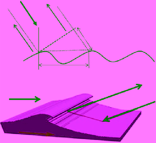
Figure 7.40
Two configurations of radar scattering mechanisms
from ocean wave: (a) Bragg scattering and (b) double bouncing.
Capillary waves that trigger Bragg scattering can be superim-
posed on gravity wave that generates the double scattering.
to devastating proportions near the coast due to reduced
water depth. Tsunami is a Japanese word, with the English
translation being “harbor wave.”
If the roughness scale of the ocean surface is much
smaller than the wavelength of the incident microwave
signal, the surface is considered to be smooth and the
scattering follows a specular pattern, producing near‐zero
backscatter. This is particularly manifested at large inci-
dence angles. Backscatter increases as the surface rough-
ness scale increases with respect to the wavelength of the
microwave signal until it reaches its peak. The peak is
triggered by a scattering mechanism called Bragg scatter-
ing. In this mechanism, the radar signal resonates with
components of the surface wave spectrum. The radar sig-
nal scatters from successive ocean waves, as shown in
Figure 7.40a. The scattering from different waves may or
may not be in‐phase because of the different path lengths
as shown in the figure. If scattering from successive waves
is in‐phase, the waves may then interfere constructively,
producing high backscatter. This is the essence of Bragg
scattering. The Bragg equation relates the ocean wave-
length
d
required to trigger the Bragg scattering to the
radar wavelength (
λ
) at an incidence angle
θ
measured
from the datum of the ocean surface:
2
d
sin
(7.105)
It is clear that the wavelength of the ocean wave has to
be almost equal to the radar wavelength for Bragg scat-
tering to occur. The wavelength range of the operational