Geology Reference
In-Depth Information
means that the emitted signal has no preferred polarization
(i.e., randomly polarized or unpolarized).
The polarization or depolarization of the scattered
radar signal depends on the surface structure and the
heterogeneity of the volume. As a rule of thumb, depo-
larization of a radar signal is caused by multiscattering
processes. This is manifested in the scattering from sur-
faces covered with dense random structures such as for-
est trees or various urban structures. For sea ice, the
multiple scattering is possible from ice blocks of a ridge
or from a volume that has inclusions in the form of scat-
tering elements (e.g., air bubbles in MY hummock ice).
The depolarization of the scattered EM wave from a
rough surface is discussed in
Fung
[1966]. The study
shows that both the quasi‐specular scattering and the
multiple scattering are responsible for the polarized
return, while multiple scattering alone is responsible
for depolarization. In a followup study,
Fung
[1967]
obtained backscatter from rough surfaces and inhomo-
geneous (anistropic) media in microwave frequencies
and concluded that depolarized backscatter measure-
ment s are much less dependent on an incident angle than
like‐polarized backscatter measurements. More informa-
tion on situations of depolarization of both radar
scattering and passive microwave emission is included
in
Fung and Chen
[2009].
regions. In addition to the physical temperature, emission
of energy is determined by the emissivity, which is also a
ratio as described later. All of the above‐mentioned coef-
ficients are wavelength dependent. It should be men-
tioned that emitted radiation is relevant only to the TIR
and microwave regions.
7.3.2.1. Reflection
Reflection takes place at the interface between two
media of different refractive indices (in the optical region)
or different dielectric constants (in the microwave region).
Part of the energy that penetrates the medium may
undergo scattering, and a portion of the scattered signal
may reach back to the reflective surface and refract across
it. This is known as internal reflection that adds to the
surface reflection. The observed reflection from any
ground cover is the summation of these two components.
This explains the high reflectivity of the snow in the VIS
region. It is not because of the “smooth” surface of the
snow but because the reflection is mainly generated from
within the composite volume where snowflakes and air
coexist. Since the Earth does not emit radiation in the vis-
ible spectrum, the reflectivity of the sunlight in the VIS
range determines the visibility of the surface.
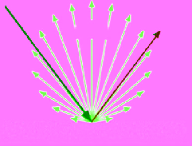
Depending on the wavelength of the incident signal
with respect to the roughness scale of the surface, when
the incident wave strikes the surface, it might be reflected
in a single direction away from the incident direction
(mirror reflection) or scattered in all directions. The first
scenario occurs if the surface is very smooth compared
to the wavelength of the incident radiation. The second
scenario occurs if the surface is rough. The scattering
then increases with roughness. In the optical domain
these two idealizations are called specular and diffuse
directions, respectively (Figure 7.16). Specular reflection
is governed by the laws of geometrical optics. The direc-
tions of the incident and reflected EM beam make equal
angles to the normal to the reflective surface. It should be
7.3.2. Reflection, Transmission, Absorption,
Scattering, and Emission
The EM wave interaction with any medium is mani-
fested in five radiometric processes: reflection, transmis-
sion, absorption, scattering, and emission. Absorption
and scattering represent losses. Each process is quantita-
tively described by a ratio. For example, the reflection
coefficient is the ratio between the amplitude of the
reflected to the incident radiation. Similar definitions
apply to the transmission coefficient, absorption coeffi-
cient, and scattering coefficients. The transmission coef-
ficient and the absorption coefficient are also known
as transmittance and absorptance, respectively (though
these terms are not universally adopted). Scattering coef-
ficient is the fractional decrease in the intensity (i.e. the
rate of emitted energy from unit area through unit solid
angle) of the scattered radiation over a given distance.
When the power ratio is used (instead of amplitude ratio),
the first three processes are defined in terms of reflectiv-
ity, transmissivity, and absorptivity. The emitted radiation
results when part of the incident energy is absorbed and
re‐radiated later to maintain thermal equilibrium with
the surroundings. Every object emits energy determined
mainly by its temperature as long as the temperature is
above absolute zero (−273.18 °C). Objects of the Earth
system emit energy in the TIR and microwave spectral
Diffuse reflection
Figure 7.16
Schematic diagram showing idealizations of
specular versus diffuse reflection.