Geology Reference
In-Depth Information
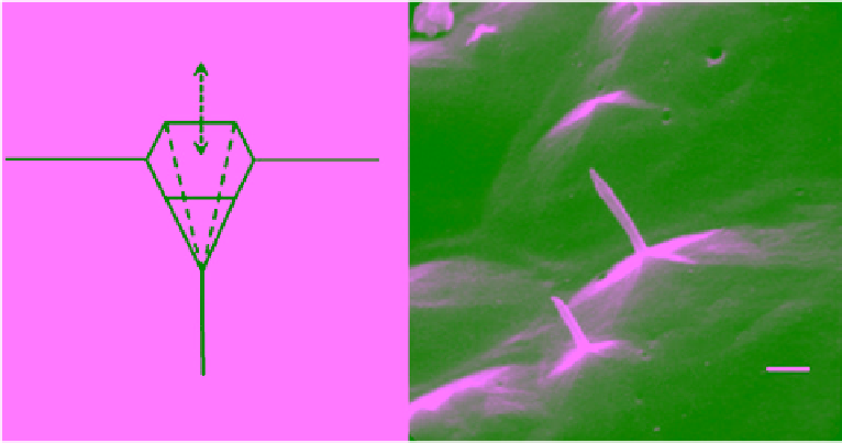
Figure 6.32
Schematic diagram of a chemically etched hexagonal pyramidal pit on basal surface at (a) the
intersection of a nonbasal dislocation and (b) scanning electron micrograph (SEM) of replica of such a pit and
associated core of the dislocation [SEM by
N. K. Sinha
, 1977b].
inside the box is controlled qualitatively by varying the
degree of closure of the top of the box and providing a
gentle flow of air around the box. Transparency of the
box allows the specimen to be observed externally with
an optical microscope without disturbing the environ-
ment inside the chamber. For the observations originally
reported in
Sinha
[1977b], concentrations of the etchant
were varied from 0.05% to 10%, temperatures from −5 to
−40 °C, the thickness of solution was up to 5 mm, and the
humidity varied to obtain a period of drying from a few
minutes to several days.
Replicas can be removed by three different methods:
1. Peeling, when the replica was to be examined imme-
diately to evaluate a particular etching procedure.
2. Melting of the ice in water just above the melting
point and allowing the film to float.
3. Allowing the ice to sublimate. This process is time con-
suming and may take up to 15 days when the temperature
is below −35 °C, but it does provide undamaged replicas.
The replicas are carefully mounted on large glass slides
with the replicated surface facing upward and observed
with a good‐quality optical microscope. Selected areas
can then be prepared for examination with an SEM by
vacuum deposition of a layer of carbon followed by a
plating of gold.
A schematic diagram for the formation of a hexagonal
pyramid‐shaped etch pit is shown in Figure 6.32a. The
sketch shows an example of a pit related to a nonbasal
dislocation intersecting a basal plane (0001). A replica of
such a pit naturally will exhibit a reverse image of the
emergence point of the core of a nonbasal dislocation. In
fact, the replicated cores (appear as whiskers in replicas)
associated with etch pits established that (a) dislocation is
a line defect and, for the first time in the history of mate-
rial science, (b) one‐to‐one correspondence between an
etch pit and a dislocation without any ambiguity. The spe-
cial cases of correspondence between hexagonal pyramidal
etch pits and nonbasal dislocations intersecting the basal
plane was established by
Sinha
[1977b]. The correspond-
ences between elongated etch pits on prismatic surfaces
and basal dislocations intersecting these surfaces were
also confirmed by
Sinha
[1978a]. Establishing such corre-
spondence between etch pits and dislocations (both basal
and nonbasal) were possible only because ice exists at
extremely high temperatures. An example of such pits for
dislocations and whiskers corresponding to the cores of
those dislocations is shown in Figure 6.32b. This micro-
graph also shows hexagonal pits without the whiskers.
In these cases, etching time was sufficient to produce only
the pits but not enough to etch deeply along the core of the
dislocation for the development of whiskers correspond-
ing to the cores. Probably the dislocations corresponding
to these pits, particularly the small pit, moved to these
positions after the beginning of the actions of the etch-
ant. The proof for showing that dislocations do move
under external forces (induced thermally or mechanically)
can be also established by the dual process of etching and
replicating technique. To prove that the hexagonal pits
due to nonbasal dislocations intersecting the basal sur-
face can actually move under stress, all that is necessary is
to microtome the surface to a mirror finish and bend the
glass plate slightly to induce stresses during etching and
replication. The dislocations move under the stresses and
produce etch tracks. An example is shown in Figure 6.33.