Geology Reference
In-Depth Information
Figure 6.26
Thermal etching box with transparent glass bot-
tom and top covers, two stainless steel rollers to support the
glass plate and DMT thin section of ice; crushed ice (not
shown) inside the box on two sides maintain high humidity.
0.5 mm
controlled further by keeping the glass plates containing ice
thin sections inside a closed chamber with near saturated
environment, as shown in Figure 6.26 containing a little
crushed ice or snow around the corners at the bottom.
If the top and the bottom covers of the thermal etching
box are transparent, as shown in Figure 6.26, thin sec-
tions can be examined with an optical microscope
through transmitted light without disturbing the environ-
ment of the sections. Polarized light can also be used to
delineate different grains and thereby bring out grain
structures. The author (N. K. Sinha) has found that sur-
face imperfections of ice thin sections can be revealed
very prominently under transmitted light, but propagat-
ing at oblique angles, rather than light traveling at right
angles to the surfaces of thin sections. This is actually
very important to remember while photographing sur-
face characteristics of thin sections of any transparent
materials, like ceramics and rocks. For ice, in particular,
the use of obliquely transmitted light has been found to
be extremely useful for micrographing sublimation pits
(Higuchi etch pits) as well as thermally or chemically
etched grain or subgrain boundaries in ice. Oblique light-
ing brings out perceptions of depth in a clear manner and
provides a pseudo‐three‐dimensional effect. Example of
the quasi‐3D effect of oblique transmitted lighting can be
seen in Figure 6.22 for sublimation pits and in Figure 6.27
for thermally etched grain boundaries in pure ice.
The conventional technique of making thin sections
and observations under polarized light has been proven
to be inadequate for fine‐grained ice but of high density,
such as common granular ice. It has been proved to be
useless if the average grain diameters are small, for exam-
ple, less than 0.3 mm. This type of hopeless situation can
be avoided in a very simple way by making use of thermal
etching. An example is shown in Figure 6.27. In this case
a drop of water at a freezing temperature was spat cooled
to simulate in‐flight icing due to the impact of super-
cooled water droplets on aircraft structures at subzero
temperatures. Following solidification on the surface of
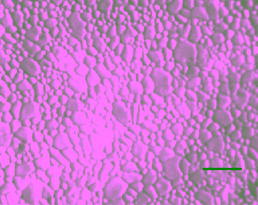
Figure 6.27
Grain size distribution in spat‐cooled (a condition
similar to in‐flight icing) and almost instantly frozen drops of
distilled water, revealed by sublimation under controlled con-
ditions; note that extremely small grains with diameters of
about 50 nm can also be revealed by this method (micrograph
by N. K. Sinha, unpublished).
an aluminum (of the type used in aircrafts) plate, the
specimen was simply placed inside a thermal etching box,
as shown in Figure 6.26, at −10 °C and let the sublimation
do the work. In this case, the micrograph was taken by
using oblique, but reflected light under a microscope.
The substructures of sea ice can be examined by ther-
mal etching in a very simple and direct manner, provided
the surfaces and thin sections are prepared by the DMT
technique. To illustrate this, a 0.33 m long full‐depth core
of FY S3‐type sea ice was sampled from the middle of
Strathcona Sound in Baffin Island, away from the shore
line, on 26 November, 1975 during a polar night. The
entire 30 km long sound was full with a uniform cover of
land‐fast sea ice. The air temperature was −32 °C and the
air was calm. Due to the presence of the snow cover, the
ice was relatively warm. Immediately after extraction, the
core was stored in a clear core bag under ambient condi-
tions until processed. The ice was columnar grained with
the
c
axis of the grains in the horizontal plane and ori-
ented preferably along the length of the sound and, there-
fore, parallel to the tidal current. Figure 6.28 shows an
optical micrograph of a horizontal thin section (prepared
using the DMT technique) at a depth of 0.3 m. The salin-
ity of this section, measured from the microtome‐shaved
ice, was found to be 12
‰
. The thin section was prepared,
using a freshly sharpened microtome blade, at −10 °C
purposely for the examinations of entrapments as liquid
in brine pockets because that was close to the in situ tem-
perature of the ice in the ice sheet under a blanket of
snow. The micrograph in the top image of Figure 6.28