Geology Reference
In-Depth Information
(a)
(b)
10
μ
m
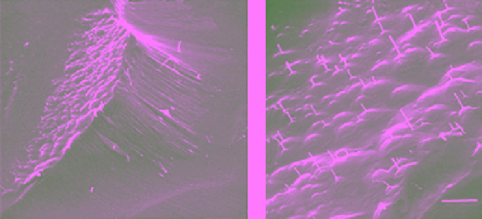
Figure 6.24
Scanning electron micrographs of a replica showing (a) a sublimation pit for ice surface with
c
axis
inclined, but
a
axis parallel to the surface; and (b) details of numerous pyramidal dislocation etch pits with dislo-
cation cores (looks like whiskers) on the inclined basal face (SEM by N. K. Sinha, unpublished).
in optical microscopes or even SEM. The specimen sur-
faces have to be chemically etched to bring out the details
of the surface structures.
Etching evokes a notion of either applying a chemical
agent on the surfaces of metallographic specimens or
immersing them in the etching solution. The objectives
are to dissolve metals away from the specimen surface
defects in a selected manner. Usually, the grain bounda-
ries are etched more rapidly than the surface of the
grains because the grain boundaries are relatively at
higher energy levels. The etching solution may also dis-
solve the various grains differentially according to the
crystallographic orientation of the surfaces exposed to
the chemicals. The etched boundaries affect the reflectiv-
ity of the light and reveal their presence when viewed
through microscopes in reflected lights. The etched sur-
face features can also be examined by the SEM for higher
magnifications and greater depth of field.
The etching of crystal surfaces and producing etch
pits is widely accepted as a powerful tool for observa-
tions of structural aspects of materials including lattice
defects and their behavior [
Gilman and Johnston
, 1956].
The problems and complexities encountered in ice, how-
ever, are significantly different from those faced in other
materials mainly because the working temperatures with
ice are so close to its melting point. Removal of the sur-
face atoms by chemical actions in addition to the simul-
taneous processes of sublimation complicates the matter
enormously for ice. However, the fact that ice is always
extremely hot also provides significant advantages over
other materials, and this has been demonstrated earlier
and more will be covered below.
Toward the end of 1940, methods for determining the
orientation of
c
axis and the size distribution of grains in
polycrystalline ice were developed by
Seligman
[1949] and
Schaefer
[1950], but not the
a
axis. In fact, attempts to
etch and replicate ice surfaces used by
Schaefer
[1950],
inadvertently led to the development of the Higuchi
method and has been presented earlier. Another high‐
temperature aspect of ice is the internal melting.
Nakaya
[1956] showed that the orientation of
a
axis can be deter-
mined, at least for single crystals, by generating Tyndall
figures inside the crystal. These figures develop due to
internal melting. The absorption of infrared radiation
from light beams is sufficient to melt the ice internally.
Kuroiwa and Hamilton
[1963] showed that a 5% or 6%
solution of Formvar in ethylene dichloride was a suita-
ble etchant for developing dislocation etch pits on the
basal plane corresponding to the emergence of nonbasal
dislocations on this surface. Dislocation etch pits on the
(0001) plane were found to be hexagonal pyramidal, in
agreement with the earlier observations of
Muguruma
[1961].The earlier investigator's conclusions on the asso-
ciation of etch pits with dislocations were based on indi-
rect, though convincing, evidence, whereas the latter
workers provided direct evidence by showing etch tracks
as evidence of the movement of dislocations under
stress. Some of these observations were later confirmed
by
Levi et al.
[1965]. A significant progress was then
made by
Kuroiwa
[1969], who looked at Formvar replicas
using a scanning electron microscope with the resolution
and depth of field required for investigating the three‐
dimensional topography of etched surfaces of ice.
However, dislocations are line defects [
Weertman and
Weertman,
1964], and the correspondence between non-
basal dislocations and pyramidal etch pits on basal plane
was established not directly but by inferences. Indirect
methods, similar to the classic examples set by
Gilman
and Johnston
[1956] for lithium fluoride, were used.
Gilman and Johnston related point‐bottomed etch pits