Geology Reference
In-Depth Information
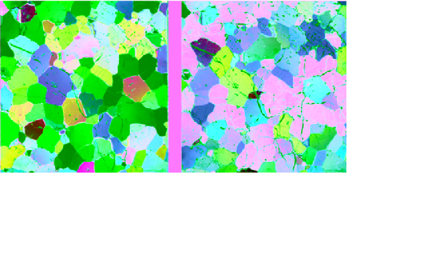
Figure 6.13
A 100 mm wide thin section of shelf ice from a block of floating ice island that was calved from Ward
Hunt Ice Shelf, Ellesmere Island, Canada as observed through cross‐polarized (left) and parallel‐polarized light
(right) (N. K. Sinha, unpublished). (For color detail, please see color plate section).
plane. These bubbles, with their dimensions comparable
to the wavelength of microwaves, may contribute to the
backscattering of incident radiations from microwave
imaging systems. It should be mentioned that some of
the ice in the Ward Hunt Ice Shelf could be as old as
3000 years.
Analyzer
Cross position
6.3.3. Scattered Light and Combined
Cross‐Polarized/Scattered Light Viewing
Ice thin section
Saline inclusions in the form of brine pockets and gas
bubbles are the primary entrapments in sea ice. Inclusions
in the form of air bubbles are a commonly observed phe-
nomenon in shelf ice and freshwater lake/river ice. The
details of these inclusions are not readily observed in
images of thin sections taken under crossed polarized
light, except for the fact they may appear as dark spots.
Often the air bubbles and brine pockets are not discerni-
ble from each other. Parallel polarized images, as
described above, are certainly useful in delineating the
inclusions. An alternative method is observing thin sec-
tions using only the diffused/scattered light from a side
illumination source at oblique incident angles. Another
method, which is often very useful, is the use of scattered
light in conjunction with polarized light images (com-
bined method). The scattered light involves sources of
unpolarized light from the inclusions in between the
polarizer and the analyzer, as shown schematically in
Figure 6.14. The diffuse reflection from a surface of a
translucent thin section of ice consists of light scattered
from the imperfections of the surface and inclusions
beneath the top surface. The scattered light may be par-
tially polarized or not polarized at all, depending on the
size of the inclusions. Therefore, only some of the light is
allowed to transmit through the analyzer. Consequently,
Polarizer
Unpolarized bottom light
Figure 6.14
Viewing of an ice thin section in a polariscope
using transmitted cross‐polarized light together with scattered
light due to diffuse reflection of light illuminated from the side at
oblique incidence angle (sketch by N. K. Sinha, unpublished).
the scattering objects (i.e., inclusions) are visible beyond
the analyzer.
To view the thin section under scattering light, only the
cross‐polarized light source (coming from the polariscope
shown in Figure 6.10) should be switched off and the
analyzer should be rotated out of the optical train.
Examples of the use of scattered light and/or combina-
tions with polarized light are given in many places within
this topic.
A unique application of the scattered‐light technique
was made in viewing thin sections of ice at the ice‐water