Geology Reference
In-Depth Information
reflections from floors or tabletops are elliptically polar-
ized with strong components in the horizontal plane, a
linearly polarizing filter can be distinguished readily by
rotating the filter while looking at the reflected light
through the filter. Make certain to buy “linearly” polar-
izing filters and not the “circularly” polarizing filters
because the salesperson may not know the difference
between these two types of polarizing filters. The autofo-
cus and light metering sensors of some modern cameras
may not function reliably with linearly polarizing filters.
For ice, the two commonly used positions are the cross
and the parallel polarizing positions. Such configurations
can only be obtained with linearly polarizing filters. These
filters come in the form of concentric rings. The outer
ring (male) has threads on the back for mounting the fil-
ter on the camera by screwing it in front of the camera
lenses. The inner ring holds the polarizing filter and can
rotate freely inside the male through 360°. For easy iden-
tification of the pass orientation, the axis of the polariza-
tion of the filter is marked with a single dot or a pair of
dots, diametrically opposite to each other, on the front of
the inner ring. While viewing through the eyepiece of the
camera, the inner ring can be rotated to get the cross posi-
tion or any desired position with respect to the polarizer.
When viewing a thin section using a polariscope, the
individual crystals can be seen in different colors, with
the best view revealed when using crossed polarizers as
explained earlier. Since the two polarizers are free to
swing in the NRC polariscope, they can be moved out of
the light train, and the specimen can be illuminated from
the side. The side light is scattered by the inclusions in the
ice and can be used for taking scattered‐light pictures.
This sidelight (without the main light of the polariscope)
enhances the appearance of air and brine inclusions in
sea ice but does not show the details of the grain struc-
tures. An alternative method of viewing is to combine the
cross‐ or parallel‐polarized light in conjunction with the
scattered light. This is described in section 6.3.3.
Figure 6.11
Goniometer or the universal stage (Rigsby type)
to sit on the freely rotatable specimen holder of the NRC
polariscope shown in Figure 6.10 (photos by N. K. Sinha,
unpublished).
(a)
(b)
C
100mm
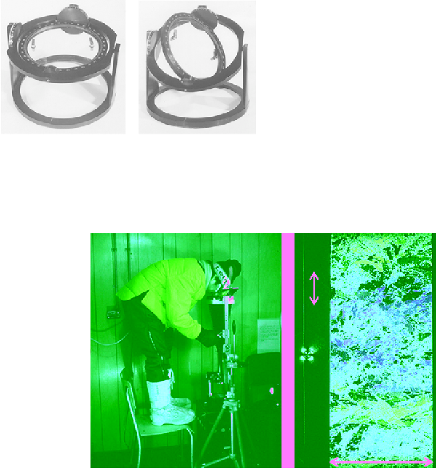
Figure 6.12
N. K. Sinha inside Mould Bay field laboratory using NRC polariscope equipped with (a) high‐resolu-
tion 4 × 5 view‐camera and (b) a 100 mm × 250 mm DMT thin section of S3‐type sea ice with average
c
axis along
the long dimension, after confined compression tests, exhibiting recrystallization; the arrow with
c
indicates the
direction of
c
axis and water current in Mould Bay; the cross on the left indicates the orientation of the cross
polarizers. (For color detail, please see color plate section).