Geology Reference
In-Depth Information
either before or after the thin sections of snow [
Satyawali
et al.,
2003;
Klein‐Paste et al.,
2007].
Different crystals with different orientations of their
c
axis (optic axis) in a polycrystalline body appear as
areas of different colors if transmitted white light is
used for viewing. However, colors are never used for
textural analysis of polycrystalline ice. The texture
analysis is made with the help of a universal stage and
positions of extinction [
Langway
, 1958]. Microstructural
aspects deal with the geometry of ice and snow crystals
and pores in a sample, whereas textural aspects involve
crystallographic orientations of ice and snow crystals
in a sample.
In practice, it is not always possible to make thin sec-
tions with parallel surfaces and within the narrow thick-
ness range of 0.4-0.8 mm. Sections thicker than this
optimum range are also useful, but the interference colors
are not the best. Nonetheless, relatively thin sections can
be made with nearly parallel surfaces by using the hot‐
plate as described above. The hot plate technique cannot
be used for sea ice if the internal structures of entrapped
brine in the form of pockets that also include air pockets.
The solid‐state, DMT technique, developed by
Sinha
[1977a], offers the best possible choice for making thin
sections with thicknesses down to about 0.1 mm required
for fine‐grained granular ice or snow masses with crystal
sizes of fractions of 1 mm (
Satyawali et al.,
2003;
Klein‐
Paste et al.,
2007].
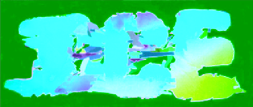
Figure 6.9
Double‐microtomed thin section (about 0.4 mm
thick) of ice alphabets viewed through cross‐polarized white
light (photo by N. K. Sinha, unpublished). (For color detail,
please see color plate section).
Demonstration of a colorful solid‐state DMT thin sec-
tion of a specially fabricated polycrystalline ice is shown in
Figure 6.9. The specimen thickness was about 0.4 mm and,
as expected from Figure 6.6, the colors are rather warm,
predominantly yellow. In this case, the three letters of the
alphabet were initially cut from vertical thick sections of
directionally solidified (DS) columnar‐grained distilled‐
water ice, classified as S1 type. In S1 ice, the cross‐sectional
diameters in the horizontal plane or normal to the direction
of heat flow and growth are large and could be 100 mm or
larger. The
c
axis of the vertically oriented columnar grains
in S1 ice tends to be in the vertical plane. Consequently, sec-
tions made in the vertical plane tend to have the
c
axis in the
plane of the sections and therefore normal to the direction
of propagation of light. Slight deviation of the
c
axis from
the plane of the section, due to the formation of subgrains
in S1 ice [see
Sinha
, 2011, for details], led to differences in
the color. Each of the letters of the alphabet in the word
“ICE” in Figure 6.9 was as large as 80 mm.
Snow or granular ice forming on floating ice covers
tends to have crystal sizes in the range of 1 mm or less.
Spat cooling and freezing of water droplets on metallic
surfaces such as in‐flight icing on aircraft wings and heli-
copter blades may have crystals with sizes only fractions
of 1 mm, around 0.05 to 0.1 mm. Usual optimum thin
sections, discussed above, required for good interference
colors may contain several grains within the depth of the
sections. Moreover, the grain boundaries in these fine‐
grained materials could be very slanted and occupy large
areas if sections are in the usual range. Optimum thick-
nesses for such materials are about 0.1-0.2 mm. This min-
imizes the width of the grain boundaries that could be
slanted. This thickness range, according to Figure 6.6
produces
R
λ
=140-280 nm. This range of retardations
produces gray or white color. Additional retardations can
be introduced, if necessary, to the beam of light to bring
the interference colors within the first two orders of
colors. This can be done by using retardation plates such
as mica sheets in between the polarizer and the analyzer
6.3. viewing and phOtOgRaphing
ice thin sectiOns
The birefringent property of ice and snow crystals is
used for revealing individual crystals in different colors
using plane‐polarized white light as explained in the pre-
vious section. The spectacular colors are very attractive
and provide the impetuous and joy for making thin sec-
tions in spite of harsh conditions of cold environment,
but the colors are incidental, not essential. Moreover,
black and white photographs were used traditionally for
measurements, not only because the photography was
cheaper (which was indeed true) but the colors were not
required for any quantitative analysis. The digital pho-
tography of today has removed the barriers of cost of
producing the photographs, but, as said before, the colors
add only marginal advantages. In fact, the use of plane‐
polarized monochromatic light sources provides better
definitions of the intercrystalline or grain boundary
regions.
Once a thin section is prepared, it has to be examined,
visually or under microscope, and photographed. To
reiterate, optical microscopes are rarely used for this
purpose, though magnification can reach 200×, because
of their limited depth of field (the distance between

