Geology Reference
In-Depth Information
(c)
(d)
Electromagnetic waves
E-field
Figure 6.1 (c, d)
Electromagnetic monochromatic wave train with linear motion from the left to the right (c) and
the uniform linear motion (double‐headed arrows for electric vector) in (d) the cross section of the beam.
relevant to microwave remote sensing is made in
section 7.3.1.
Figure 6.1c illustrates a beam of EM monochromatic
wave traveling with a linear motion from left to right.
Figure 6.1d shows the corresponding uniform linear
motion in the cross section of the beam. The double‐
headed arrows in Figure 6.1d represent the electric vector,
i.e., the polarization of the waves. If electromagnetic
waves are generated from a source with their electric field
oriented randomly, the beam of waves is called unpolar-
ized or “randomly polarized.” Rays of sunlight or lights
from lamps and electric bulbs are randomly polarized.
Solar radiation diffused through clouds or fogs are also
randomly polarized, but that's not the case for sunlight
scattered from the sky. Blue sky light on clear days is
somewhat polarized. Lights reflected from nonmetallic
surfaces, such as tree leaves, water bodies, and floors are
also partially polarized.
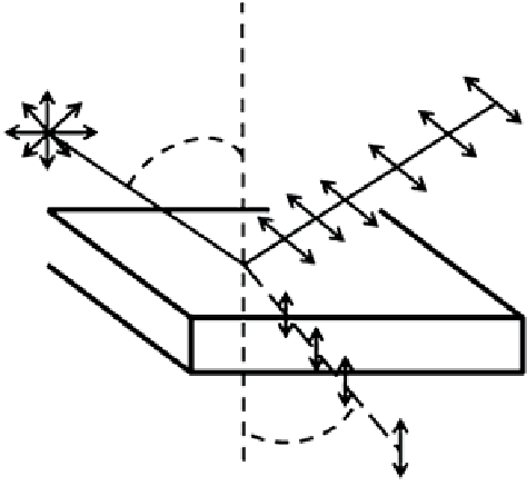
Figure 6.2 illustrates a special case of reflection and
refraction of an unpolarized beam of monochromatic
light for a critical case of the incidence angle, called
Brewster angle (
θ
iB
). The plate could be any transparent
material, crystalline or amorphous like glass, but if the
plate is made from a single crystal of ice (Ih) with its
optics axis (
c
axis) normal to the surface of the plate,
then the Brewster angle is close to 52.6°. The specialty of
this particular example is not in the characteristics of the
angles of reflection or refraction. Like any flat and trans-
parent plate, the angle of reflection in this case is also
equal to the Brewster angle,
θ
iB
, and if the corresponding
Brewster angle of refraction is denoted by
θ
rB
, then the
refractive index of the plate (
n
p
), like any angle of inci-
dence, is given by
n
p
= sin
θ
iB
/sin
θ
rB
. However, for this spe-
cial case of incident angle, both the reflected and the
refracted beams are plane polarized, as shown in
Figure 6.2. Plane of polarization of the reflected and the
refracted beams are shown by the double‐headed arrows
for the electric vector. Note that the reflected beam is
polarized in the plane parallel to the surface, whereas the
refracted beam is strongly polarized in a plane 90° to the
plate surface. For the illustrated configuration of the ice
plate and for
λ
=589.3 nm,
n
p
= 1.309 corresponding to
θ
iB
of about 52.6°.
Plane-polarized
light
Unpolarized
light
θ
iB
Ice plate
θ
rB
Figure 6.2
Polarization of light by reflection from a special case
of a single‐crystal ice plate with its optic axis (
c
axis) normal to
the surface and the angle of incidence equals the Brewster
angle,
θ
iB
, is 52.6° (Sketch by N. K. Sinha, unpublished).
In this specially illustrated case, the plane of polariza-
tion of the refracted light is parallel to the orientation of
the optic or
c
axis. For this reason, the beam is tradition-
ally called an “ordinary ray” and the refractive index
is usually denoted by
n
o
. In birefringent materials such
as ice (presented next in section 6.1.2), the refractive
index,
n
e
, for a light beam with plane of polarization
normal to the optic axis is slightly different and is called
an “extraordinary ray.” These two names, ordinary and
extraordinary, have no special significances other than
the historic relevance; other names could have been more
appropriate.
When an unpolarized beam of light is transmitted
through a linearly polarizing filter, it becomes linearly
polarized as shown in Figure 6.3. The set of double‐
headed arrows indicate the “pass direction” or the orien-
tation of the electric vector. If another polarizer (called
analyzer) is inserted in the way of the propagating polar-
ized beam with its pass direction oriented at 90° to
that of the polarizer, no light will be transmitted.