Geology Reference
In-Depth Information
water salinity in a small, but sufficiently deep, laboratory
tank is virtually impossible. The main idea was to avoid
excessive cost, and complexities of storing and shipping ice
from the Arctic to the laboratory in Ottawa. The driving
forces were, therefore, very strong to reproduce S3 type of
sea ice, representing the bulk ice of natural ice covers, in suf-
ficient quantities for conducting laboratory strength tests in
Ottawa. However, the establishment of an excellent “work-
ing” laboratory in Mould Bay (Figure 5.2b) at virtually no
cost to NRC eliminated any real need for making S3 ice in
Ottawa. However, S3 type of SY ice obtained from Mould
Bay during the spring of 1983 was then used as the seed plate
and distilled water in the tank to prove that completely
desalinated SY ice with its natural subgrain structure can
indeed be reproduced successfully in Ottawa. The method of
reproducing columnar‐grained S2 ice from seed crystals has
actually been tried successfully at Laval University, Canada,
by
Barrette et al.
[1993]. It was shown by using S2‐type fresh
water ice as seed crystals, in a saline water tank, that S2 type
of saline ice, with subgrain structures along with entrapped
brine pockets at the subgrain boundaries, can also be repro-
duced in the laboratory. Since the sea-ice research funds are
decreasing and expensive field trips are becoming things of
the past, reproducing S3 type of “sea-ice” in laboratories will
be the trend in the future for conducting experiments on
microstructure-property relationships.
If one projects the aging process to a third year, depend-
ing on how much surface melt takes place, one can end up
with either third‐year ice, which is by definition MY ice
or with a new SY ice if the total thickness of the previous
SY melts away. The properties of these two ice types in
the third year would be different as would the two SY ice
types as compared from the second to the third year.
Thus, the aging processes are very complex and depend
particularly on the history of the amount of ablation and
how it affects the near‐surface properties of the ice.
These changes in the aging process are clearly observable
in the 90 GHz passive microwave data collected with the
Naval Research Laboratory P‐3 aircraft in the Mould
Bay region in 1981 [
Hollinger et al.,
1984]. The spread of
emissivity for old ice varies between 0.68 and 0.85. This
high variation in emissivity makes it very difficult to
select the proper value for inclusion in sea ice algorithms
to determine the fraction of old ice present.
temperature drops suddenly and tensile forces, greater
than the tensile strength of the top ice, are generated at the
ice surfaces. This can readily happen if the snow cover is
not sufficiently thick to reduce the effect of the induced
thermal shock. Once nucleated, the surface cracks may
propagate down into the ice under favorable conditions.
Thereafter, the cracked segments can be moved away by
the current under the ice and/or wind. Narrow water chan-
nels are formed and subjected to rapid freezing if cracks
develop in the middle of the winter. In sea ice, this tends to
occur when the ice sheet is thin, rich in brine content, and
therefore significantly weak. Leads also develop in rela-
tively thicker ice if it is warm and weak, and the oceanic
conditions are rough. In general, leads provide easier pas-
sages (and there lies the importance of space‐borne remote
sensing) for winter navigation in the sub‐Arctic regions,
especially for Canada, throughout the winter seasons.
An attempt was made at Mould Bay in April 1983 to sim-
ulate such a formation of a lead in the middle of winter
conditions. This attempt was made for examining the rapid
freezing processes and the effect on microwave backscatter.
Since the air temperatures varied between −46° and −20°C
during this field trip from 5 April to 10 May of 1983, it was
thought to be ideal for conducting such an experiment. The
exercise also led to the exposure of a total of 12 m (4 × 3 m)
long interface between the old ice and new ice in a 3 m
squire pit in the ice cover and this came as a bonus.
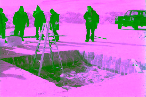
For creating a crack in the ice and producing a newly
formed narrow water channel for simulating a lead, a
3 m × 3 m pit was cut with chain saws to a depth of about
0.7 m in the SY ice sheet at a location between stations
8 and 9, but closer to station 9 (see Figure 5.17 for station
locations). The open‐cut pit is shown in Figure 5.26. To the
5.1.3. Interface Between Old and New Ice in SY
Ice Cover
Leads are often created when a floating ice sheet cracks
due to wave actions, thermal stresses, or both, and cracked
sections move apart. Cracking apart of ice sheets is gener-
ally caused primarily by the wave actions compounded
with the activities of the wind. However, cracks can also
be generated under relatively calm conditions, if the air
Figure 5.26
AES‐NRC team beside a 3 m × 3 m (about 0.7 m
deep) pit they prepared near station 9 in Mould Bay in April
1983; note the sharp demarcation line near the bottom
between lighter SY ice and darker new (FY) ice (photo by N. K.
Sinha, unpublished).