Geology Reference
In-Depth Information
(c)
(a)
(b)
0.00
F
A
B
R
I
C
0.25
0.50
Second year
First year
0.75
Frazil
1. 00
Grain Shape
78
9
0
5
10
1. 25
Bubbles
Density, K/g/m
3
Salinity, ppt
Te xture
(d)
(e)
0.44m
Interface
Thin sections
0.52m
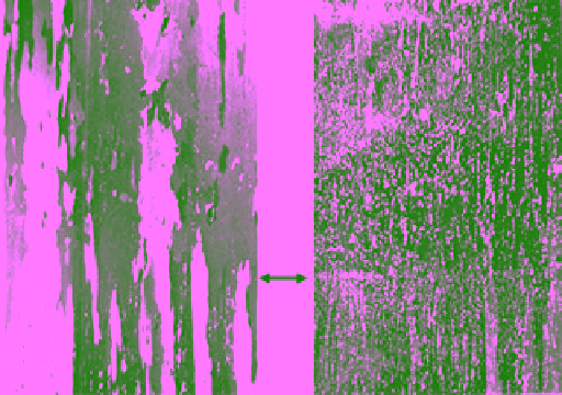
Figure 5.19
Vertical profile of (a) density, (b) salinity, and (c) combined texture, fabric, and thin section under
cross polarized (left) and scattered light (right) of (only of the top 0.52 m) S3‐type ice at station 9 in Mould Bay,
April 1983 displaying continuity of columnar grains across the sharp interface between SY ice and new growth.
Details of the interface region are shown in (d) and (e) (photo by N. K. Sinha, unpublished).
layer of highly concentrated small circular air bubbles.
The air bubbles within the fabric were predominantly
circular in shape and located at the subgrain boundaries.
About 82% of the bubbles had diameters of less than
1 mm. A question remains as to the structural details of
the ice in the vicinity of the old/new ice interface and,
more importantly, the highly porous ice near the surface,
just below the snow cover, which may be the prime
sources of backscattering for
c
‐band microwave radia-
tion. The characteristics of the top of the ice surface will
be presented first.
From the measured low density (about 775 kg/m
3
), as
can be seen in Figures 2.18 and 2.19, and the general
appearance of the surface, particularly the white color, it
was natural to think of the ice near the surface as snow
ice. To explore the in situ structure and texture of the
surface layers of SY ice (particularly relevant to micro-
wave scattering), snow cover was removed very carefully,
essentially following techniques used in archaeological
investigations. The result of careful surface cleaning is
shown in Figure 5.20. Surprisingly, the surface structure
was far from that expected for recrystallized or solidified
snow slush. The photograph clearly shows elongated
cross‐sectional views of the voids exposed to the surface.
Moreover, it also shows that the long dimension of the
voids in the horizontal plane tends to be oriented normal
to the direction of the axis of the channel and hence
the water current indicated by the double‐headed arrow.