Geology Reference
In-Depth Information
material (of dominant volume fraction) and another
material regarded as an inclusion. Inclusions are assumed
to be ellipsoidal of identical shape and size but randomly
spaced within the host material. They can be oriented or
nonoriented. The model incorporates also an assumption
that the average size of the inclusion element is an order
of magnitude less than the wavelength of the incident
radiation. Therefore, only the overall volume of the inclu-
sions, rather than the size of inclusion elements, appear in
the formulation. The expression for the average dielectric
constant
m
of a two‐phase dielectric mixture is
i
Inclusion volume
fraction < 0.1
h
*
=
h
E
Z
Fictitious host
ellipsoid
E
X
E
Y
i
h
V
i
i
h
(3.84)
Inclusion volume
fraction > 0.1
mh
1
A
i
1
u
*
*
=
m
where
V
i
is the volume fraction of the inclusions (i.e.,
brine pockets or air bubbles in the case of FY and MY
ice, respectively),
h
and
i
are the complex dielectric con-
stants of the host material (i.e., pure ice in this case) and
the inclusions. Both are assumed to be isotropic (scalar
quantity), which is a valid assumption for sea ice. In fact,
h
of the pure ice is constant = 3.15; * is the effective die-
lectric constant for the region immediately surrounding
the inclusion element. It can be anisotropic (vector quan-
tity) if the inclusions have an anisotropic shape or a domi-
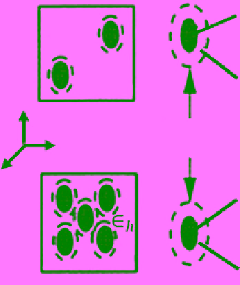
nant orientation. The value of * is determined based on
an assumption concerning the mutual interaction between
inclusion elements. If the volume fraction of the inclu-
sions is less than 0.1, the mutual interaction can be
neglected and * may be made equal to
h
. If the volume
fraction is larger than 0.1, the mutual interaction can be
accounted for by assuming that each inclusion element is
surrounded by a mixture of the host material and inclu-
sions. In this case * =
m
(Figure 3.27). In equation (3.84)
A
u
is the depolarization factor of the ellipsoid inclusion
particle along its
u
axis (
u
=
a
,
b
, or
c
). Their sum is equal
to unity [
Landau and Lifdhitz,
1975]. The above model
assumes that inclusions have an identical ellipsoidal shape
but can be randomly spaced within the host material.
They can also be oriented or nonoriented (Figure 3.28).
Applications of the PVD model [equation (3.84)] are
introduced in the following for three commonly observed
shapes of inclusions in sea ice: sphere, oriented needle,
and randomly oriented needle. Detailed derivation of the
dielectric constant expression for each case is presented.
It should be noted that
Hallikainen
[1977] also evalu-
ated the applicability of the same PVD model by using
four different assumptions regarding the shape of brine
pockets. Results from using the parallel‐needle assump-
tion were found to be closest to the measurements pre-
sented in
Hoekstra and Capillino
[1971].
Stogryn
[1987]
discussed the tensor properties of the dielectric constant
Figure 3.27
Assumptions regarding the dielectric constant of
the host material in the immediate vicinity of the inclusions
[
Shokr and Sinha,
1995].
E
Z
E
X
E
Y
Figure 3.28
Idealization of inclusion shapes, elliptic (top),
needle (middle), and spherical (bottom) with oriented and
random distributions used in the dielectric mixing model
[
Shokr and Sinha,
1995].
of sea ice. He developed a set of self‐consistent equations
that account for the dielectric properties of a variety of
ice types over a range of temperatures. A brief review of
modeling and experimental investigation of the dielectric
properties of natural and simulated sea ice is presented in
Hallikainen and Winebrenner
[1992]. An analytical study
for obtaining bounds on dielectric constant of composite