Global Positioning System Reference
In-Depth Information
x
1
2
3
4
5
6
7
8
9
10
11
12
13
14
15
16
17
18
19
20
21
22
23
24
25
26
27
28
29
30
31
32
33
34
35
36
37
38
39
40
41
42
43
44
45
e
y
z
[70
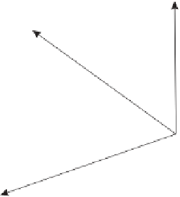
Figure 3.5
The satellite body-fixed coordinate system.
Lin
—
-3.
——
Nor
PgE
Th
e symbol
p
denotes the SRP in the direction of the sun. With the sign convention
of
Equation (3.79),
p
should be positive. The other parameter is called the
Y
bias.
Th
e reasons for its existence could be structural misalignments, thermal phenomena,
or
possibly misalignment of the solar panels with the direction of the solar photon
flu
x. The fact that a
Y
bias exists demonstrates the complexity of accurate solar
ra
diation pressure modeling. Table 3.2 shows the effects of the various perturbations
ov
er the period of one day. The table shows the difference between two integrations,
on
e containing the specific orbital perturbation and the others turned off. It is seen
th
at SRP orbital disturbance reaches close to 100 m in a day. This is very significant
co
nsidering that the goal is centimeter orbital accuracy. Over a period of 1-2 weeks
th
e SRP disturbance can grow to over 1 km.
[70
3.
1.4.4 Eclipse Transits andYaw Maneuvers
Orbital determination is fur-
th
er complicated when satellites travel through the earth shadow region (eclipse). The
TABLE 3.2
Effect of Perturbations on GPS Satellites over One Day
Perturbation
Radial
Along
Cross
Total
Earth flattening
1335
12902
6101
14334
Moon
191
1317
361
1379
Sun
83
649
145
670
C
2
,
2
, S
2
,
2
32
175
9
178
SRP
29
87
3
92
C
n,m
, S
n,m
6
46
4
46
(
n, m
=
3
...
8)
Source:
Springer et al., 1999.
Note:
The units are in meters.