Global Positioning System Reference
In-Depth Information
1
2
3
4
5
6
7
8
9
10
11
12
13
14
15
16
17
18
19
20
21
22
23
24
25
26
27
28
29
30
31
32
33
34
35
36
37
38
39
40
41
42
43
44
45
P
2
s
P
1
h
2
s
h
1
R
R
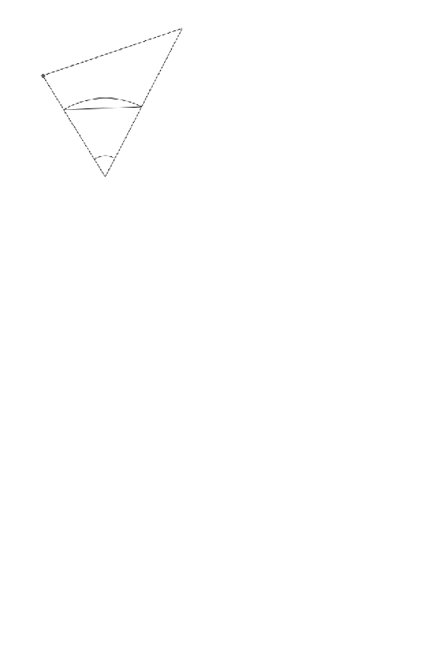
Figure 9.4
Slant distance versus geodesic.
[32
9.1.1.2 Distance Reduction to Geodesic
The slant distance
s
(not to be
confused with the scale correction of Section 8.2 which uses the same symbol) must
be reduced to the length of a geodesic
s
. Figure 9.4 shows an ellipsoidal section along
the line of sight. The expression for the length
s
of the geodesic is typically based on
a spherical approximation of the ellipsoidal arc. At this level of approximation, there
is no need to distinguish between the lengths of the geodesic and the normal section.
The radius
R
, which is evaluated according to Euler's equation (B.8) for the center of
the line, serves as radius of curvature of the spherical arc. The expressions in Table
9.2 relate the slant distance
s
to the lengths of the geodesic
s
.
One should note that computing the length of the geodesic requires knowledge
of the ellipsoidal heights. Using orthometric heights might introduce errors in the
distance reduction. The height difference
Lin
—
-
——
No
PgE
[32
h
1
in Expression (e) of Table 9.2
must be accurately known for lines with a large slope. Differentiating this expression
gives the approximate relation
∆
h
=
h
2
−
µ ≈−
∆
h
µ
d
d
∆
h
(9.1)
where
d
h
represents the error in the height difference. Surveyors often reduce the
sla
nt distance in the field to the local geodetic horizon using the elevation angle
∆
TA
BLE 9.2
Reducing Slant Distance to Geodesic
cos
2
sin
2
1
R
=
α
α
+
(d)
M
N
s
2
− ∆
h
2
µ =
1
+
1
+
(e)
h
1
R
h
2
R
2
R
sin
−
1
2
R
s
=
ψ =
R
(f)