Global Positioning System Reference
In-Depth Information
1
2
3
4
5
6
7
8
9
10
11
12
13
14
15
16
17
18
19
20
21
22
23
24
25
26
27
28
29
30
31
32
33
34
35
36
37
38
39
40
41
42
43
44
45
[32
Lin
—
1.9
——
Lon
PgE
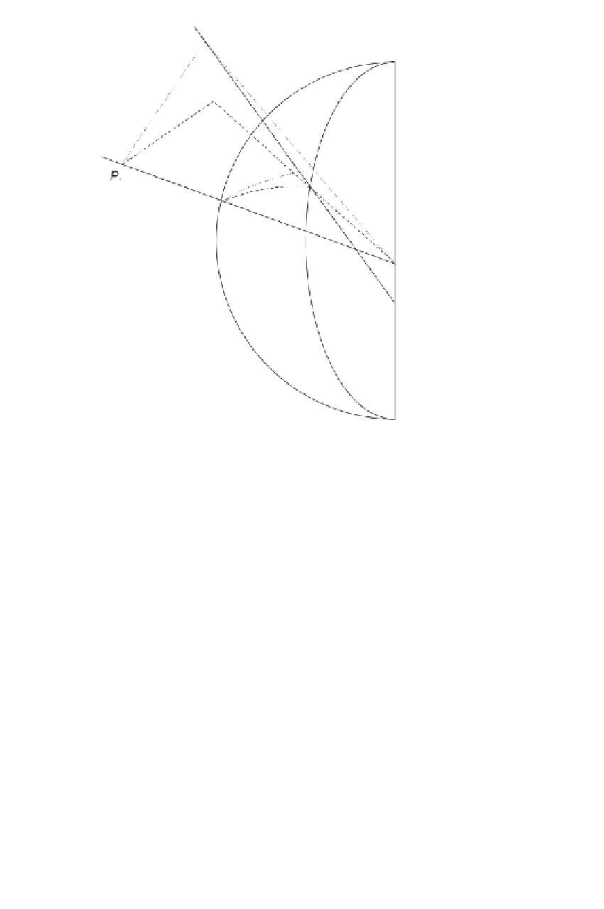
Figure 9.1
Normal section azimuth versus height of target.
[32
plane defined by the ellipsoidal normal of
P
1
and the space point
P
2
. The represen-
tatives of these space points are located along the respective ellipsoidal normals on
the surface of the ellipsoid and are denoted by
P
1
and
P
2
. The dotted line
P
1
to
P
2
denotes the intersection of this normal plane with the ellipsoid. The azimuth of the
normal section defined by the ellipsoidal normal at
P
1
and the surface point
P
2
is
α
.
α
− α
The angular difference
(
)
is the reduction in azimuth due to height of
P
2
; the
expression is given in Table 9.1. The height of the observing station
P
1
does not affect
the reduction because
α
is the angle between planes.
The need for another angular reduction follows from Figure 9.2. Assume that two
ellipsoidal surface points
P
1
and
P
2
(labeled
P
1
and
P
2
in Figure 9.1) are located at
TA
BLE 9.1 Reducing Geodetic Azimuth to Geodesic Azimuth
α
1
− α
1
[arcs]
=
0
.
108 cos
2
ϕ
1
sin 2
α
1
h
2[km]
(a)
α
1
− α
1
[arcs]
=−
0
.
028 cos
2
ϕ
1
sin 2
α
1
s
[km]
2
(b)
100
∆α
[arcs]
=
0
.
108 cos
2
ϕ
1
sin 2
α
1
h
2[km]
−
0
.
028 cos
2
ϕ
1
sin 2
α
1
s
[km]
100
2
(c)