Global Positioning System Reference
In-Depth Information
1
2
3
4
5
6
7
8
9
10
11
12
13
14
15
16
17
18
19
20
21
22
23
24
25
26
27
28
29
30
31
32
33
34
35
36
37
38
39
40
41
42
43
44
45
[30
Lin
—
-
——
No
PgE
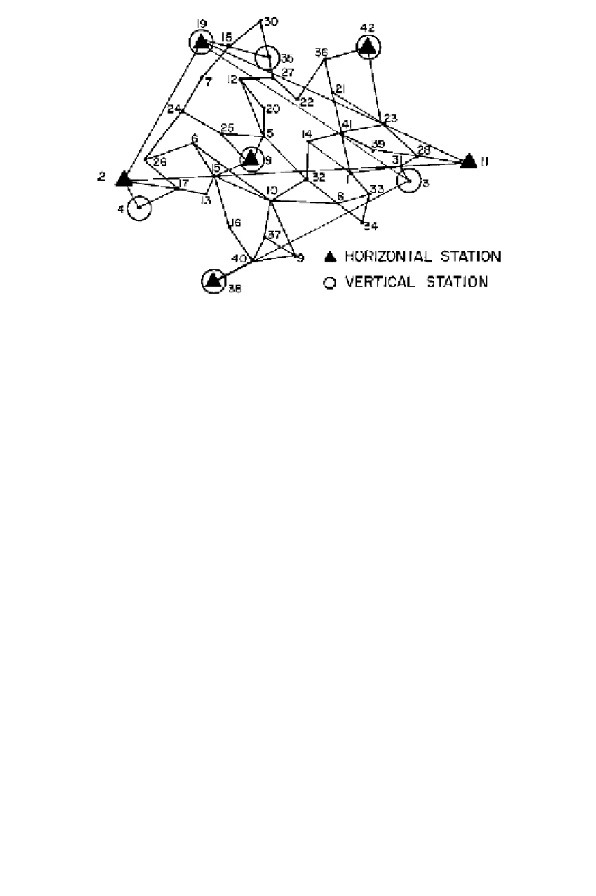
Figure 8.2
Existing geodetic control and independent baselines.
The dots in that figure represent the directions of the semimajor axis of the ellipsoids
of standard deviation for each station. These directions tend to be located around
the center of the satellite constellation. The standard ellipses show a systematic
orientation in both the horizontal and the vertical planes. This dependency of the
shape of the ellipses with the satellite constellation enters into the adjustment through
the 3
3 correlation matrices. With a better distribution of the satellites over the
hemisphere, the alignments seen in Figure 8.3 for the horizontal ellipses do not occur.
Because satellites are observed above the horizon, the ellipses will still be stretched
along the vertical.
The coordinates of the polyhedron of stations are given in the coordinate system
of the broadcast ephemeris; at the time of the Montgomery County survey this was
WGS72 (today this would be WGS84 or the latest ITRF). The positions of the poly-
hedron stations can be expressed in terms of geodetic coordinates relative to any el-
lipsoid, as long as the location of the ellipsoid is specified. For example, the minimal
constraints could be specified by equating the geodetic and astronomic latitude and
longitude of station 29, and equating the ellipsoidal height and the orthometric height.
The ellipsoid defined in that manner is tangent to the geoid at station 29. By com-
paring the resulting geodetic heights with known orthometric heights at the vertical
stations, we can construct a geoid undulation map (with respect to the thus defined
ellipsoid). The geoid undulations at other stations can be interpolated to give ortho-
metric height from the basic relation
H
×
[30
N
.
The method described above can be generalized by not using the astronomic
position for station 29. The geodetic latitude and longitude, such as the NAD83
positions, can be used as minimal constraints. The thus defined local ellipsoid is not
tangent to the geoid at station 29. The undulations with respect to such an ellipsoid
are shown in Figure 8.4.
=
h
−