Global Positioning System Reference
In-Depth Information
1
2
3
4
5
6
7
8
9
10
11
12
13
14
15
16
17
18
19
20
21
22
23
24
25
26
27
28
29
30
31
32
33
34
35
36
37
38
39
40
41
42
43
44
45
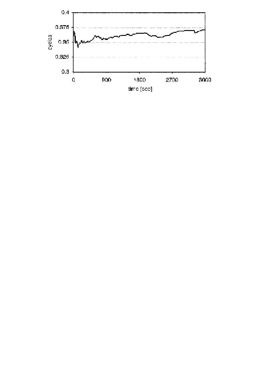
Fi
gure 7.17 DDRB differences between GPS and GLONASS with fixed GPS-GPS and
G
LO-GLO double-difference ambiguities.
[27
pr
km,
1
is an estimate of the double-
difference L1 receiver hardware bias, labeled DDRB, as applied to GPS and
GLONASS. Figure 7.17 shows the estimated DDRB every 10 sec for a 1-hour series
of observations of a 10 m baseline at Irwin, California, using 3S Navigation receivers
that measured L1 pseudorange and carrier phases of GPS and GLONASS satellites
on June 12, 1998. All GPS satellites were observed; there were four GLONASS satel-
lites available during that hour. Figure 7.17 seems to suggest that one could further
strengthen the combined GPS and GLONASS solution by modeling the DDRB as a
constant.
The conventional double differencing of carrier phase observations has the well-
known form
Since
N
pr
km,
1
∆ξ
Lin
—
-2.
——
Nor
PgE
is an integer the fractional part of
[27
f
1
c
ρ
ϕ
pq
km,
1
,
GPS
pq
km
N
pq
km,
1
,
GPS
=
+
(7.123)
f
1
c
−
f
1
f
1
d
t
km
f
1
c
ϕ
rs
km,
1
,
GLO
r
km
s
km
N
rs
km,
1
,
GLO
=
ρ
−
ρ
+
−
(7.124)
Th
e GLONASS double differences depend on the receiver clock error and the fre-
qu
encies. This dependency is demonstrated in Figure 7.18, which shows the functions
f
1
km
=−
f
1
−
f
1
d
t
km
f
1
ϕ
ps
p
km,
0
+ ∆
ps
km,
0
+
km,
1
,b
−
c
ρ
c
ρ
(7.125)
where the observations have been corrected for the topocentric satellite distances
which have been evaluated for the known station coordinates and translated by
ps
km
for the lines to go through zero at the first epoch. The observational data are the
same as those used in Figure 7.17. The order of the lines corresponds to that of the
frequencies
f
1
. Equations (7.123) and (7.124) are suitable for estimating the double-
difference integers, as long as the receiver clock differences are estimated at the same
time.
∆