Global Positioning System Reference
In-Depth Information
1
2
3
4
5
6
7
8
9
10
11
12
13
14
15
16
17
18
19
20
21
22
23
24
25
26
27
28
29
30
31
32
33
34
35
36
37
38
39
40
41
42
43
44
45
τ
(ϑ)
1
cos
(ϑ)
m
τ
(ϑ)
≡
0
)
=
(6.58)
τ
(ϑ
=
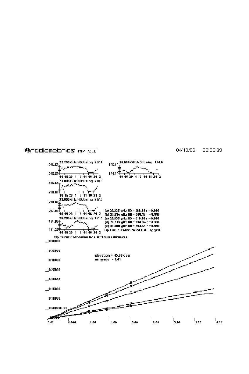
Figure 6.11 shows an example of radiometer calibration using tipping. The opacity is
plotted versus air mass. Looking straight up, the opacity of one air mass is observed.
Looking at 30°, the opacity of two air masses is observed, etc. Since opacity is linear,
we can extrapolate to zero air mass. At zero air mass, we have
m
τ
(ϑ)
=
0 because
there is no opacity for a zero atmosphere.
The calibration starts with a radiometer voltage (noise diode, labeled ND in Figure
6.11) reading
N
bb
of an internal reference object, which one might think of as a black
body. The physical temperature of that object is
T
bb
. Let
G
denote the initial estimate
of the gain factor (change in radiometer count reading over change in temperature).
The observed brightness temperature at various zenith angles, measured by tipping
the antenna, is then computed by
[21
1
G
(N
bb
−
T(ϑ)
=
T
bb
−
N(ϑ))
(6.59)
Lin
—
3.8
——
Nor
PgE
[21
Figure 6.11
Tipping curve example.
(Courtesy of R. Ware, Radiometrics Corporation,
Boulder)