Global Positioning System Reference
In-Depth Information
where
e
k
is the unit vector pointing from the station to the satellite and
p
k
is the
1
2
3
4
5
6
7
8
9
10
11
12
13
14
15
16
17
18
19
20
21
22
23
24
25
26
27
28
29
30
31
32
33
34
35
36
37
38
39
40
41
42
43
44
45
ρ
respective unscaled topocentric vector.
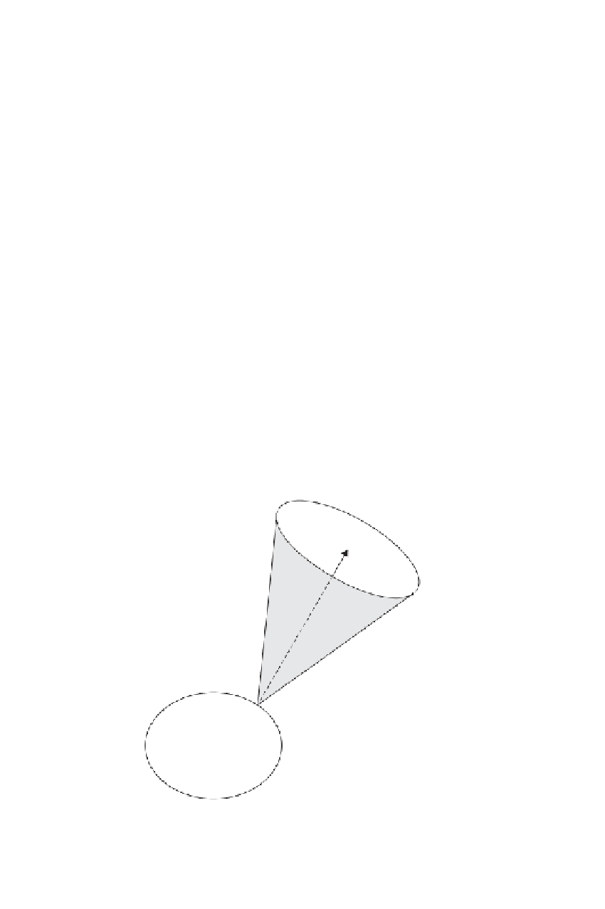
Figure 5.1 shows a situation where all satellites are located on a circular cone.
This is obviously a special situation. The vertex of the cone is at the receiver. The
unit vector
e
axis
specifies the axis of the cone. For all satellites that are located on the
cone, the dot product
e
k
·
e
axis
=
cos
θ
(5.49)
is
constant.
e
k
represents the first three elements of row
i
of the design matrix.
Th
erefore, (5.49) expresses a perfect linear dependency of the four columns. Another
cr
itical configuration occurs when the satellites and the receiver are located in the
sa
me plane. In this case, the first three columns of the design matrix fulfill the cross-
pr
oduct vector function
[18
e
k
=
e
k
×
n
(5.50)
Lin
—
2.0
——
Nor
PgE
where
n
is a constant vector.
Critical configurations usually do not last long because of the continuous motion
of the satellites. The critical configurations present a problem only in continuous
kinematic or very short rapid static applications. The more satellites are available,
the less likely it is that a critical configuration will ever occur.
In relative positioning, one can encounter critical configurations as well. Clearly,
the satellites cannot be located on a perfectly circular cone as viewed from each of the
[18
e
axis
θ
earth
Figure 5.1
Critical configuration on a circular cone.